As electronics have become more advanced, so has the equipment used to measure their signal behavior and system performance. In the realm of EMC compliance, oscilloscopes are one of the important tools used to measure signals, hunt down noise sources, and identify time-domain measurements that may contribute to radiated or conducted emissions. Without a properly selected probe, an accurate oscilloscope measurement is not possible.
Most probes supplied with an oscilloscope are the passive type, possibly with up to 10x attenuation, and moderate bandwidth (50 or 100 MHz). For the newer test engineer who is building up their lab and capabilities, what factors should you examine when selecting probes for accurate scope measurements?
If you only need passive probes, with bandwidths reaching below 1 GHz, then the main specs to consider are:
– Probe bandwidth
– Attenuation
– Compensation
IMPORTANT OSCILLOSCOPE PROBE SPECIFICATIONS
Probe Bandwidth and Equivalent Circuits
The bandwidth of an oscilloscope probe limits the range of signals that can be accurately measured with an oscilloscope. The term “accuracy” as used here means that the signal captured with an instrument has the closest resemblance to the actual signal behavior in the system being examined. Therefore, looking at an arbitrary input signal in the frequency domain, the probe bandwidth needs to exceed the signal bandwidth. Mathematically, we would write:
BW (Probe) > BW (signal)
Basic probes that are packaged with most lower-cost oscilloscopes will have probe bandwidths reaching ~100 MHz. More advanced oscilloscopes might be supplied with a probe that offers much higher bandwidth, or a specialized probe must be purchased to reach higher bandwidth.
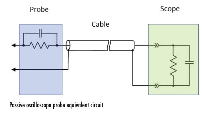
Bandwidth is further defined based on the equivalent circuit of an oscilloscope probe. The typical circuit model describing probes is shown below.

The basic parallel RC circuit model shown above is applicable to most oscilloscope probes without applied compensation, and thus they exhibit limited measurement bandwidth through via low-pass filter behavior. Another way to think of this is in the time domain; the input capacitance and the probe’s parallel resistance will limit the responsiveness of the probe to a fast input AC signal. In other words, we would have two effects:
• The amplitude of a measured harmonic signal will appear lower if the probe bandwidth is too low
• The edge rate of a measured switching signal will appear slower if the probe bandwidth is too low
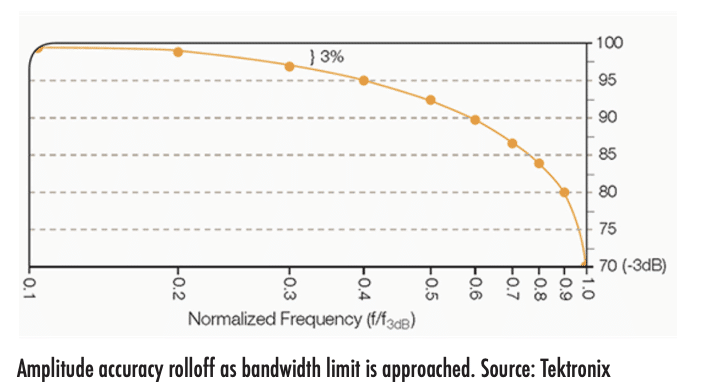
The roll-off in amplitude of each frequency component in a broadband spectrum can be seen in the transfer function for a parallel RC circuit, again assuming a probe is uncompensated. If we set define the probe’s bandwidth limit as the -3 dB attenuation point, then the amplitude measurement accuracy can still exceed 95% up to about 40% of the probe’s rated bandwidth. In other words, your 100 MHz probe is only going to give very highly accurate measurements up to about 40 MHz. Some scope vendors (e.g., Keysight) will quote this “flat response” range as being up to 50% of the bandwidth specification.

Probe Compensation
Every oscilloscope probe, along with the oscilloscope’s front-end, has a defined input capacitance that influences the bandwidth and impedance matching for a desired attenuation level. To counterbalance the input capacitance on the scope and the cable’s capacitance, the probe’s capacitance can be adjusted with a precision variable capacitor. This process is known as oscilloscope probe compensation.
Probe compensation is performed manually while monitoring measurement of a reference waveform or oscillator; this reference waveform is normally a square wave with fixed amplitude that can be accessed on the front port of the scope. This typically involves adjustment of a variable capacitor with a screw or dial, which is built into the oscilloscope probe at the scope-end of the cable. This modifies the capacitance seen by the signal as it reaches the input of the oscilloscope. While this method is commonly implemented for passive probes, compensation can also be applied in active probes (see below), which may involve adjusting the capacitance before the amplification stage in the probe.
When the square wave is monitored during compensation adjustment, the edges of the wave will exhibit overshoot or undershoot when excessive or insufficient compensation is applied, respectively. Verification is done visually; when the probe is properly compensated, the waveform measured with the probe will appear most closely to that of a true square wave.
The function of compensation that produces this response is two-fold:
• When undercompensated, the variable capacitor reduces the amplitude of high-frequency components without limiting the bandwidth.
• When overcompensated, the variable capacitor band-limits the response, and the scope produces an overshoot artifact through its sampling action.
In both scenarios, if the probe remains imperfectly compensated, a measured signal would appear distorted, but the probe user might not realize the probe is producing an inaccurate result.
Probe Attenuation
Basic probes that come in-the-box with an oscilloscope may have an attenuation setting, which is switchable between 1x and 10x attenuation values. Attenuation drops the signal level that enters the oscilloscope, but this is only one possible reason for applying >1x attenuation. The more important reason for applying attenuation has to do with loading of test circuits with low output impedance.
In general, to prevent the probe and scope from altering the signal behavior by loading the test circuit, we require the following condition:
Z (probe + scope) >> Z (circuit)
In other words, if the circuit under test has higher output impedance, you would want to increase the attenuation to the 10x value. If the signal being measured has low amplitude but the circuit has high output impedance, a more advanced probe may be needed to ensure the measured signal is accurate while still being visible above the scope’s noise floor.
More Advanced Measurements
When more advanced (in other words, higher frequency, higher voltage, and/or lower amplitude) measurements need to be performed, the simple pin/hook lead probe with a ground lead probably won’t do the trick. Although the probe might have sufficient bandwidth to do the job, the input of these probes will have excessive inductance, will require excessive compensation, or will be unable to measure the signal (e.g., for differential signals). Alternative probe types include:
• Compact probes
• Probes terminated to 50 Ohm impedance
• Differential-mode probes
• Active probes
• Current probes
• High-voltage probes
Each of these deserves its own discussion for which we don’t have room in this article, but will instead reserve for a future issue.


