Introduction
The telecom industry has undergone rapid development in the past several decades. Digital communications methods have advanced, requiring increased bandwidth and frequency coverage. This advancement has complicated an RF measurement system’s capability to accurately characterize system components. The 3rd Generation Partnership Project (3GPP) provides modern broadband mobile communication guidance. This development is chronicled in the evolutionary steps known as 2G, 3G, 4G, and now to the 5G stage currently being launched. A review of how the air interface layer changed through this evolution will help explain how measurement systems often need to be upgraded to meet the new performance criteria.
1.0 2ND GENERATION
2G modulation was the early format to move from analog modulation to digital modulation schemes. And building off of analog bandwidth and frequency coverage, the only thing to be added within the measurement system was time domain considerations to match the modulation transmitter gating.
2.0 3RD GENERATION
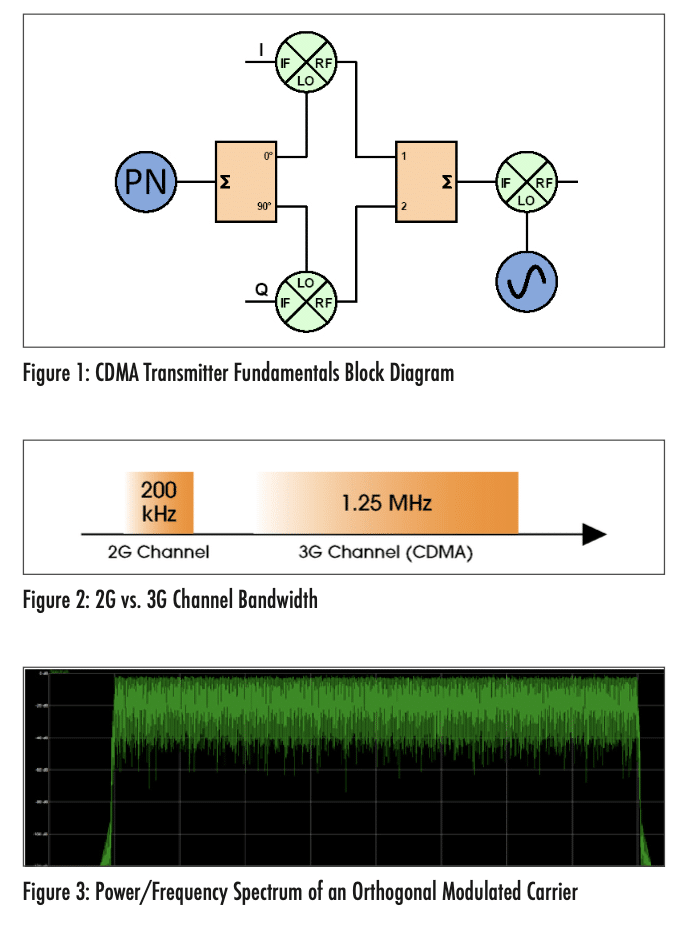
3G represented a significant advancement in digital communication. Military developments in spread spectrum technology spun off into the commercial space leading to Code Division Multiple Access (CDMA) and the higher data rate wideband CDMA (WCDMA) shown in Figure 1. As shown in Figure 2, this scheme used a Pseudorandom number waveform (PN) and quadrature modulation that required more bandwidth than the previous 2G channels. Additionally, the orthogonal modulation used has extensive peak power excursions, as seen in Figure 3.

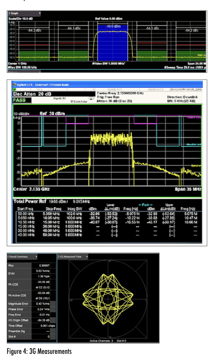
3G RF measurement systems could no longer use traditional CW techniques used for many decades as these cannot accurately represent wideband orthogonal modulation. Consequently, significant investment was required in both signal generation and signal analysis. Vector signal generators are required along with signal analyzers capable of demodulation and spectral measurements such as Adjacent Channel Power (ACP), Spectral Emissions Mask (SEM), and Error Vector Magnitude (EVM), as seen in Figure 4. * Due to a demand for more spectrum for broadband mobile communication, moving to 3G increased the spectrum from 450 MHz to 6 GHz.

* Concurrent with 3G development were advances in fixed wireless technology commonly called WIFI/WLAN. This also uses orthogonal modulation and uses the s
An example of a 3G RF measurement system is shown in Figure 5. This type of setup is used to characterize the RF components in the 3G radio head. It consists of a multichannel power supply for active devices, a signal generator capable of vector modulation, and a spectrum analyzer. Network analyzers may also be capable of 3G modulation/analysis and S-Parameter measurement.
The signal generator is a significant upgrade from 2G capable models. These Vector Signal Generators (VSG) employ arbitrary waveform generation (ARB) and I/Q modulation capability. The ARB sample rate determines the bandwidth potential, which must exceed the channel bandwidth of the desired 3G signal, which is a maximum of 5 MHz. Due to the very high peak-to-average power excursions of 3G modulation, the linear output power of the signal generator is often limited. A pre-amplifier is required to provide nondistorted signals to the Device Under Test (DUT).
For the pre-amplifier, a Class A amplifier is the best choice. Its frequency range should be broad enough to cover the entire 3G spectrum and be able to provide the additional non-distorted signal required by the DUT. Since DUT failures may present a very high mismatch, the amplifier should be ruggedized to 100% return power
The power supply is used for active device bias, which is a simple but vital part of the RF test bench. Current sense lines must be employed to compensate for voltage drops on high-current devices. Overvoltage limiting is desired to protect the DUT from overvoltage transients.
The DUT, if active, should use bypass capacitance on the test circuit board, which will supply surge current energy for RF bursts and peak-to-peak power excursions. For precise efficiency calculations, a directional coupler and power meter are used to determine the exact power at the output of the DUT calculations.
In addition to covering the 3G frequency + harmonics, the spectrum analyzer may be configured for predefined measurements based on 3GPP specification. If EVM is measured, a vector demodulation option is required.
3.0 4TH GENERATION
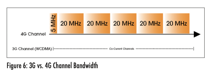
4G, otherwise known as Long Term Evolution (LTE), increases channel bandwidth to 20 MHz per channel and can include 5 contiguous channels to 100 MHz total bandwidth. Figure 6. The RF test bench remains much the same, with the exception that the VSG must increase ARB bandwidth to greater than 100 MHz.

4.0 5TH GENERATION
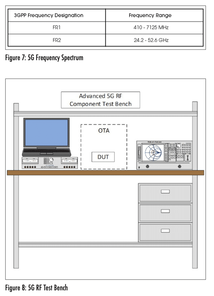
5G is a paradigm in mobile communications. More than a simple evolution, this generation introduces new protocols and is called New Radio (NR). Significant increases in bandwidth and latency are keystones for this new standard. Overcrowding in the current 3GPP spectrum designated as Frequency Range 1 (FR1) and bandwidth requirements has pushed the upper-frequency range (FR2) to 24.25 – 52.600 GHz, as shown in Figure 6. FR1 measurement systems will overlap 4G system capability. However, the move to FR2 with a bandwidth up to 400 MHz will require significant investment in new measurement systems capable of those high frequencies. Test equipment manufacturers are developing test equipment and methods to alleviate the considerable cost of a new test bench. These methods may include a box solution capable of making all the RF measurements, including saturation, Intermodulation Distortion (IMD), and S-Parameters. RF cables and connectors must be low loss and length minimized. On-chip antennas will require an Over the Air (OTA) test chamber, seen in Figure 7.

CONCLUSION
The history of evolving wireless communications has shown a continuing need to upgrade measurement systems. As we continue to evolve within the telecom industry, it is expected that this requirement will continue. The frequency spectrum and bandwidth will only increase. Test specifications will mandate additional changes to the required test equipment. Capital investment in new equipment should be expected to keep up with the ever-changing demand for more data bandwidth.


