Many companies would welcome a full EMC compliance test chamber if it weren’t for budget and real estate considerations. Yet, they would like the opportunity to develop a low-cost troubleshooting solution for assessing radiated emissions and radiated immunity prior to going off for formal compliance testing.
While I’ve written many articles [References 1 to 8] on how to perform your own emissions or immunity pre-compliance testing, a simple tabletop TEM cell may be just what you’re looking for, if all you need is to try various fixes and make quick comparisons.
A TEM (or transverse electromagnetic field) cell is basically an expanded two-port 50-Ohm transmission line or strip line. The device under test (DUT) – usually a small circuit board or sub-assembly – is placed on an insulated spacer underneath, or on top of, the central septum.
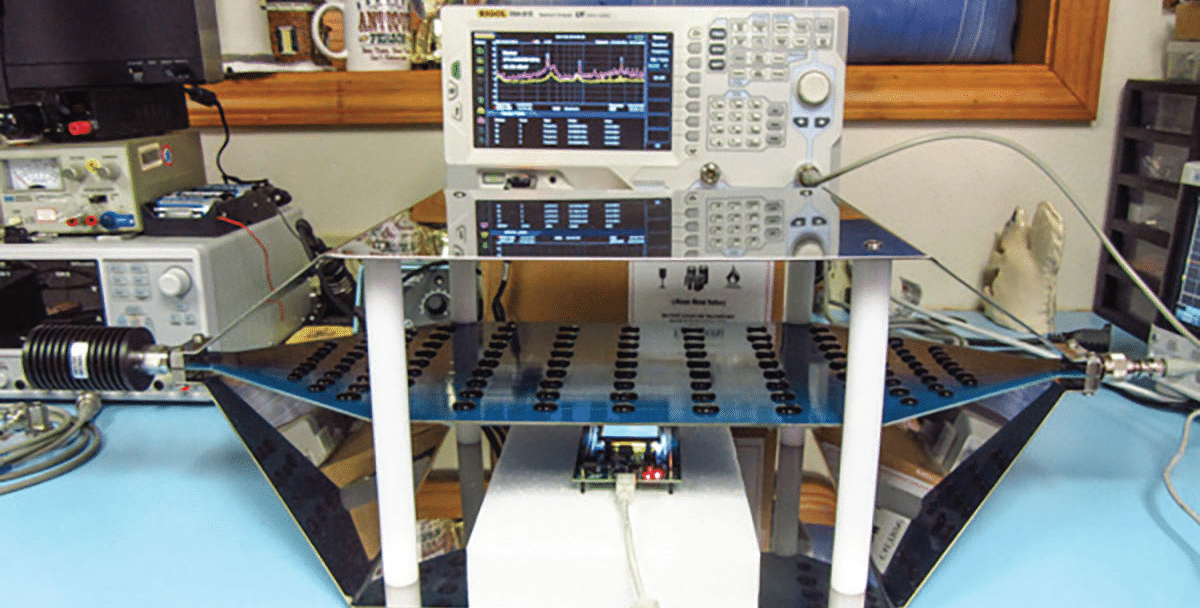
For radiated emissions testing, a spectrum analyzer is connected to one port and a 50-Ohm termination to the other (Figure 1).
A DC block is a wise choice for protection of the spectrum analyzer in case some voltage from the DUT contacts the septum.

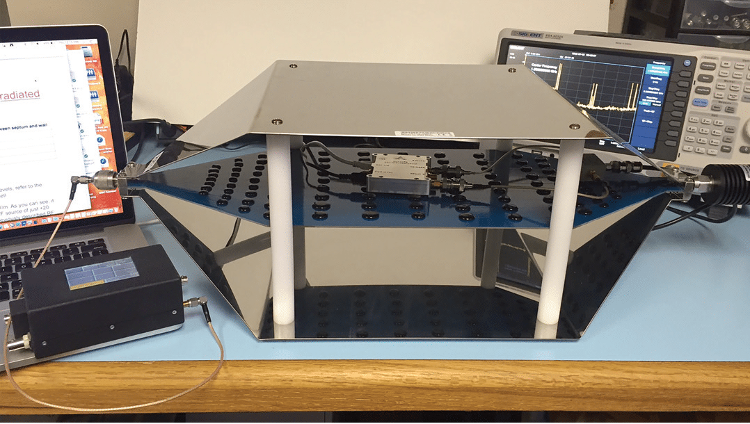
For radiated immunity testing, the spectrum analyzer is replaced with an RF generator, with the 50-Ohm termination remaining (Figure 2).

The TEM cell I’ll use for this article is manufactured by Tekbox Technologies.
These are all available in the U.S. from Selig Electronics. Check the Tekbox web site for distributors in other parts of the world.
The Tekbox TEM cell design is quite robust, and uses heavy gauge stainless steel top and bottom plates and high quality hardware and “N” connectors. Most TEM cells suffer from higher order wave modes, which limit the usable bandwidth.
The Tekbox design is unique in that the central FR4-based epoxy-fiberglass septum is designed as individual parallel strips with an array of distributed resistors connecting them together in parallel. Consequently higher order wave modes and resonances are suppressed.
Each resistor is covered with a silicon-based protective bond, as seen in Figure 5 below. This helps flatten and extend the frequency response.
The TBTC2 model I used for this article was essentially flat out to 1 GHz. Tekbox manufactures three sizes of TEM cells, TBTC1 (5 cm septum height), TBTC2 (10 cm septum height), and TBTC3 (15 cm septum height).
I’ll be using the mid-sized TBTC2 for the measurement examples in this article. This model will easily fit on top of your workbench.
All TEM cells are provided with a 25-watt 50-Ohm termination, a wideband DC block, and short N-N coaxial cable.
The Tekbox design uses an “open” cell design, for ease of use in installing and evaluating DUTs. However, the open design also allows the reception of ambient signals, which can complicate the emissions measurements.
Consequently, you’ll want to characterize a baseline (ambient) measurement prior to measuring the DUT, so you can observe the difference emission profile.
These TEM cells are all designed for small DUTs, such as circuit boards or small subassemblies. Larger products could be tested in a similar – but larger – cell, called a GTEM.
A GTEM is basically half of a TEM cell, but with RF absorber in one end. The larger models can easily fit a piece of tabletop equipment.
TEM CELL EVALUATION
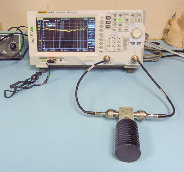
Before setting up the emissions or immunity tests, I wanted to pretest the performance of the 50-Ohm termination (Figure 3 and 4) and frequency response of the cell itself (Figure 5).
The analyzer used was the Rigol DSA815TG spectrum analyzer with tracking generator.
For the termination return loss test, I also used a Mini-Circuits ZFDC-25-5 20 dB (0.1 to 2000 MHz) directional coupler.


RADIATED IMMUNITY TESTING
Testing radiated immunity simply requires connecting an RF source at one end of the TEM cell and terminating the other end in 50 Ohms. The E-field generated is 90-degrees to the plane of the interior septum and reasonably uniform.
It doesn’t require much RF signal level to create rather large E-field levels within the cell. Tekbox provides a formula and chart for each model TEM cell (refer to their user manual for details).
In the case of the TBTC2 used in this example, the calculated field levels are depicted in Table 1.
To calculate the power required for a given E-field level between septum and lower (or upper) wall of the TEM cell, you can use the formula: E = V/d where V is the RMS voltage of the applied signal and d is the distance between septum and lower (upper) wall.
This is based on the simplified assumption that the E-field would be perfectly homogeneous/evenly distributed.
A more practical formula is E = V*Cor/d where Cor is a correction factor for the average field strength over the volume of the DUT derived from the analysis of the field distribution over the cross section of the cell.
Assuming the DUT is placed in the center of the cell and in the middle between bottom wall and septum, we can use the simplified formula with sufficient accuracy.
For model TBTC1: d = 5 cm and E = (√(P*50Ω))*20
For model TBTC2: d = 10 cm and E = (√(P*50Ω))*10 (used for this article)
For model TBTC3: d = 15 cm and E = (√(P*50Ω))*6.66

Place the DUT on an insulated spacer if used in the lower septum area.
In the example of Figure 6, I placed it in the upper chamber on top of the insulating pads. The important thing is to keep it some distance away from the top or bottom steel plates or from the inner septum.
Any connecting cables to the DUT will also be irradiated, which is a good thing, because many immunity issues are due to poorly terminated cables.
During troubleshooting, try to replace the DUT in the same physical location each time in order to reduce the number of variables. It might be a good idea to mark the placement of the EUT and tape down any connecting cables.
Most radiated immunity standards, such as IEC 61000-4-3, require either a 3 or 10 V/m field level. As you can see, you can easily achieve this with about 10 mW (+10 dBm).
Levels exceeding 200 V/m for military and automotive applications can be achieved with just 10 watts.
One caution: When performing any radiated immunity test with an open TEM cell, such as the Tekbox design, it should be conducted inside a shielded chamber to avoid potential interference to existing communications or broadcast systems.
RADIATED EMISSIONS TESTING
While measuring radiated emissions using a TEM cell will not necessarily compare with a measurement using a calibrated EMI antenna at a 3 or 10m test distance, it should provide a quick look at the overall emissions profile of the DUT and allow for quick troubleshooting.
Remember, when troubleshooting radiated emissions, the important point is relative changes.
Keep in mind, lowering the emission level of a harmonic by 10 dB does not necessarily equate to a 10 dB reduction when measured at a 3m or 10m test range.
In this case, it is not required to perform the testing in a shielded chamber. However, if used outside of a chamber, you’ll tend to receive ambient signals from various communications systems and broadcast transmitters.
You’ll want to save a baseline plot of the ambient signals prior to performing any emissions testing. I generally use Trace 1 to capture a minute, or so, of the ambients using Max Hold mode on the analyzer. Then I’ll use Trace 2 for the actual emissions plot. See Figure 8 for an example.
For this example, I’m measuring the emissions from a ST Microelectronics STM32 F4 Discovery embedded processor board.
The general-purpose board uses an ARM/Cortex-M4 core with LCD display and several I/O ports. The processor clock runs at 270 MHz.
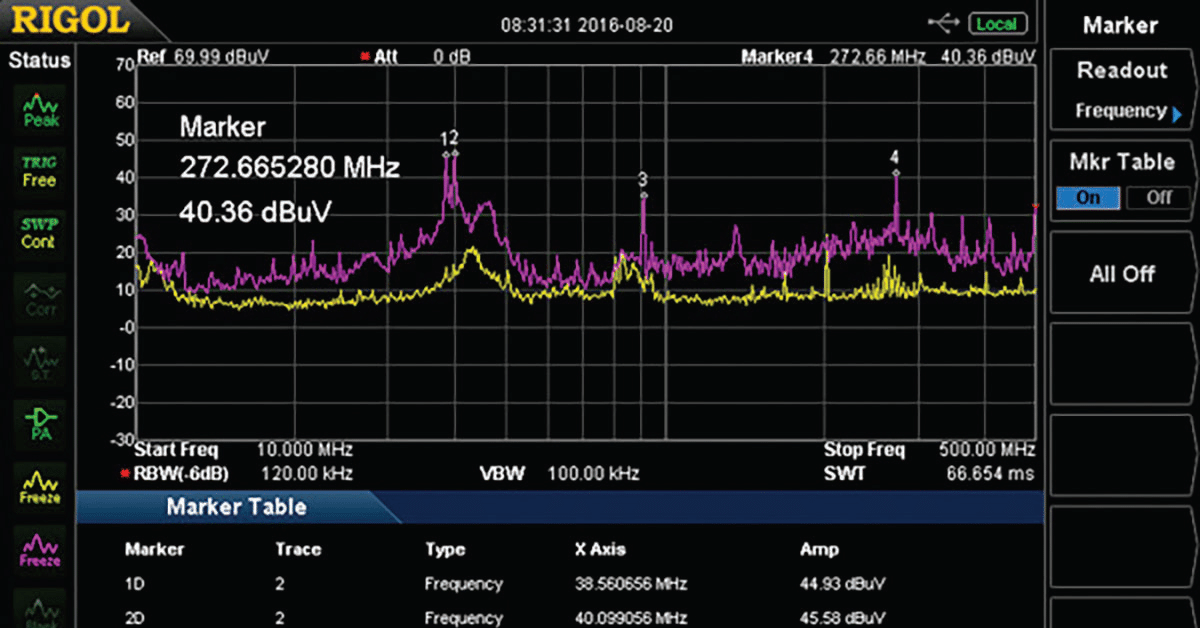
As you can see, the TEM cell can detect the entire emissions profile simultaneously – a marked improvement over performing the test in a regular EMI chamber – where harmonic emissions
must be measured recorded one at a time.
I’ve placed markers at the peak harmonics and activated the marker table feature of the Rigol DSA815TG to aid in evaluating and troubleshooting the emissions. The processor clock at 270 MHz can easily be seen.
SUMMARY
In summary, a TEM cell, such as the Tekbox model can be a useful tool for both radiated emissions and radiated immunity troubleshooting.
The device under test must be physically small enough to fit with some room to spare, between either the top plate and septum or septum and bottom plate, so this is somewhat restrictive, depending on the product.
In general, most small PC boards or subassemblies should work fine.
REFERENCES
- Advanced radiated emissions troubleshooting setups with the Rigol DSA815
- Review: The Red Oak Canyon “RF Pro Touch” RF generator
- High-powered radiated immunity precompliance testing on your workbench
- Troubleshooting EMI on your bench top
- Using current probes to estimate E-fields
- Assembling a Low Cost EMI Troubleshooting Kit – Part 1 (Radiated Emissions)
- Inexpensive Radiated Immunity Pre-Compliance Testing
- The HF Current Probe: Theory and Application
