As an EMC consultant, it seems that lately I’ve run into many client projects where radiated immunity has cropped up as the major issue. One reason for this may be the trend in using digital and analog circuits that are powered by 3.3 volts, and lower, which decreases noise margins significantly. Sensitive analog circuitry is also greatly affected.
The compliance testing for radiated immunity for most commercial products is based on the international standard, IEC 61000-4-3, and is usually performed from 80 to 1,000 MHz (sometimes to 2,000 MHz) at e-field levels from 3 to 20 V/m, depending on the product environment or application. Some military, vehicular or aerospace applications require testing to 200 to 1,000 V/m, and frequencies up to 18 GHz or more.
The RF signal is generally modulated by a 1,000 Hz AM sine wave modulation set to 80% for commercial testing, and short duration (as little as 1%) pulsed modulation for military and aerospace testing. The modulation is designed to test for “audio rectification” issues. For example, if the 1000 Hz modulation is rectified by semiconductor junctions, or in audio or other analog circuitry, it could cause bias upsets, or otherwise upset sensitive analog circuitry. For military applications, the pulse modulation serves to simulate radar interference. Strong external RF fields can:
- Reboot the system
- Disrupt of analog or digital circuitry
- Create false readings on displays
- Cause loss of data
- Halt, slow or disrupt data transfer
- Cause high bit errors (BER)
- Cause a change of state in the product (mode, timing, etc.)
- Introduce noise in measurements
- Cause a loss of sensitivity of measurement systems or receiver systems (radios)
In this article, I’d like to describe several low cost methods for creating strong RF fields, which may be used to characterize the RF susceptibility of your product.
License-Free Radio Transmitters
One low-cost technique for quick troubleshooting is to use one of the license-free portable Family Radio Service (FRS) FM two-way radios to transmit close to the sensitive areas of the product (Figure 1). These radios transmit near 465 MHz with a power level of 1/2 Watt. While limited in frequency range, many RF susceptibility problems have been located and resolved using this simple tool.

Other (mostly) license-free tools would include a portable CB radio (27 MHz) and a transmitting cellular (or PCS) mobile phone (varies from 700 to 1900 MHz). Table 6.1 lists several (mostly) license-free transmitters that may be used to test radiated susceptibility in select frequency bands. The GMRS transmitter requires a license.
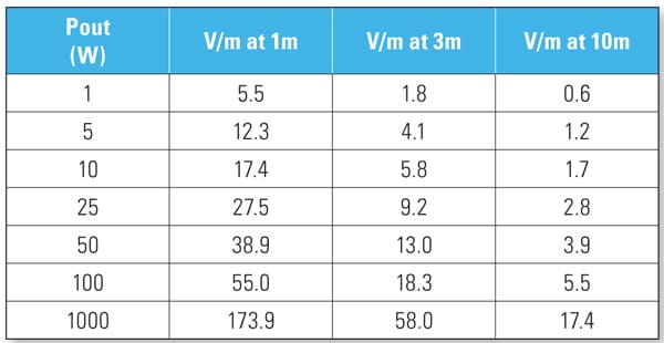
Using Equation 1, we can calculate the expected E-field level in volts/meter given the transmitter output power in watts. Table 1 indicates some E-field levels for various power levels.

Bench Top RF Generators
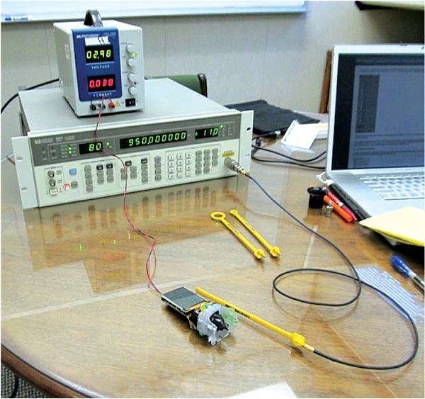
Another very good troubleshooting technique that’s tunable over a range of frequencies is to obtain a bench top RF generator and connect this to a small E-field or H-field loop probe (Figure 2). Generators that can produce at least +10 to +20 dBm work the best – the higher, the better. A plus would be the ability to apply 80% AM-modulation to the RF at 1000 Hz. This will more closely match the requirements of the immunity standard. This will produce an intense RF field (up to 10 V/m, or more), which may then be probed around cables, connectors or internal circuitry. You’ll need some way to monitor the proper operation of your product. Watch for disruptions during the probing.
If the small loop probes cause no susceptibility to the product, try taking a longer piece of wire and wrapping it with loose turns around and along the length of each I/O or power cable to couple in the RF more efficiently. Then connect this wire to the RF generator output.
While I’ve seldom needed it, in extreme cases, you may need to obtain a 10 to 20 W broadband power amplifier to boost the RF output from the generator. You could use a simple dipole antenna, such as a TV rabbit ears or DIY dipole antenna made from two lengths of wire cut to the approximate quarter wavelength (each side) of the frequency band that may be an issue and connect one side to the shield and one to the center wire of a coax cable.
Note that this test with the power amplifier should be performed in a shielded room to prevent interference to existing communications or broadcast services.
USB-Controlled RF Synthesizers
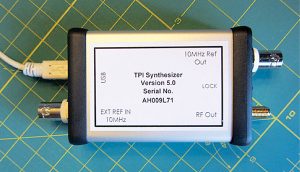
Recently, there have been a handful of small USB-powered RF synthesizers available at low cost. One affordable solution is the “TPI Synthesizer” from Trinity Power, Inc. (http://www.rf-consultant.com). This small module can produce up to +17 dBm and can tune from 35 to 4400 MHz in user definable steps of as little as 1 kHz. It is USB-controlled and includes PC software that controls frequency, sweep limits, step size and three levels of power output. You can also control or sweep the power level in definable steps. I’ve successfully used the software with my Windows 8.1 OS operating under Parallels 9 on my Macbook Pro laptop.
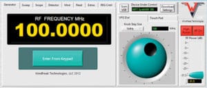
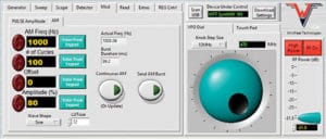
Another good option is the Windfreak Technologies “SynthNV” shown in Figure 5 (http://www.windfreaktech.com), which also includes the means to AM or pulse-modulate the RF. This RF generator tunes from 35 to 4400 MHz in 1 kHz steps and can produce up to +19 dBm output into 50 Ohms. While more than double the cost of the TPI Synthesizer, it also has the means to measure RF power levels and can be configured as a simple network analyzer. The RF output is also variable up to +19 dBm (almost 100mW).
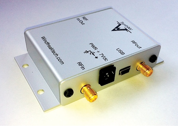
It is also USB-controlled using provided software based on National Instruments Labview. The Labview “engine” is provided at no extra charge. There’s also a simple controller software available based on the Android OS.
The SynthNV uses basically the same Analog Devices ADF4351 PLL synthesizer IC as the TPI Synthesizer, so the RF output and higher order harmonics look much the same.
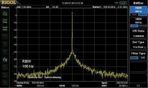
As mentioned in the caption of Figure 4, one potential disadvantage of both these synthesizers is that the second order harmonic is just 10 dB down from the fundamental, so during immunity testing, you’re effectively testing at a couple frequencies simultaneously – the fundamental at, say +19 dBm and the second harmonic at +9 dBm. Admittedly, this is a 10:1 power ratio, so may not be that much an issue. The third harmonic (and higher order) is another 8 dB down (or more), so probably doesn’t enter into the equation.
By attaching an H-field or E-field probe to the output, you can probe interior areas of your product’s PC board and discover sensitive areas that may need filtering or shielding. The nice thing about adding 1000 Hz 80% AM modulation is that it can help reveal “audio rectification” issues (generally in analog circuitry). This occurs when semiconductor junctions act as detectors and rectify the modulated RF, causing bias changes in op-amps, for example.
One thing I noticed during my testing and review of the SynthNV is the regular narrow glitches occurring during the peak modulation cycles. These can only be seen on a very fast oscilloscope (1 GHz bandwidth). I suspect, however, these glitches would not be a real issue during immunity troubleshooting. If anything, they may “over-test” the product being characterized. The designer is looking into this anomaly.
I might also point out that due to the “fractional-N” PLL, it’s not possible to exactly tune the modulation frequency to 1000 Hz. The closest it will get is 1008 Hz.
Measurement of Near Field Probes
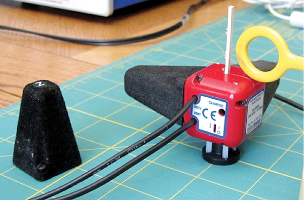
To help characterize the expected E-field levels from various near field probes (both E-field and H-field), they were measured using an ETS-Lindgren field sensor. The probes were either driven by the TPI Synthesizer or SynthNV synthesizer at the full power of each (+17 to +19 dBm output).
The three sizes of Beehive Electronics H-field and the Com-Power H-field probes were measured at various frequencies from 50 to 1300 MHz. See Figure 10.
The E-field probes were a bit flatter in response, as you might expect, because they don’t have much of an effective L-C network, being essentially electrically short monopole antennas. See Figure 11.
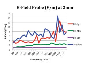
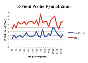
The advantage of the near field probes is that the field level falls off rapidly with distance, thus it’s easier to evaluate separate sections of your circuitry to determine the precise areas of susceptibility. See Figure 12 for a plot of field level versus distance. By 3 to 4 cm, the field is essentially 1 V/m, or less.
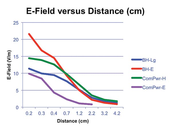
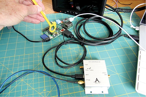
Figure 13 shows me probing a Raspberry PI embedded processor. By sweeping the probe around the PC board and I/O cables at various frequencies, you can be fairly sure your product will operate OK during the actual compliance testing. If you’re wondering, the Raspberry PI was immune to the RF levels I was able to introduce.
In summary, these simple and low cost tools can help you perform a pre-qualification assessment on your product well prior to taking it out for compliance testing. This could save you a lot of time and money. In brief:
- RF generators can drive near E-field or H-field probes to create strong localized E-fields for pre-compliance testing.
- There are low-cost RF synthesizers available now that may replace larger bench top instruments.
- Localized RF fields of 2 to 15 V/m may be generated to help diagnose radiated immunity issues with a product.
ABOUT THE AUTHOR
Kenneth Wyatt, Sr. EMC Engineer, Wyatt Technical Services, LLC, holds degrees in biology and electronic engineering and has worked as a product development engineer for 10 years at various aerospace firms on projects ranging from DC-DC power converters to RF and microwave systems for shipboard and space systems. For over 20 years, he worked as a senior EMC engineer for Hewlett-Packard and Agilent Technologies in Colorado Springs where he provided comprehensive EMC design and troubleshooting services and managed the product compliance test facility. During that time, he provided EMC training and corporate leadership for EMC.
A prolific author and presenter, he has written or presented topics including RF amplifier design, RF network analysis software, EMC design and troubleshooting of products and use of harmonic comb generators for predicting shielding effectiveness. His specialty is EMI troubleshooting and is a co-author of the popular EMC Pocket Guide. He has been published in magazines such as, RF Design, Test & Measurement World, EMC Design & Test, Electronic Design, EDN, InCompliance, Interference technology, Microwave Journal, HP Journal and several others. He coauthored The EMC Pocket Guide (SciTech Publishers) and writes The EMC Blog for www.EDN.com.
Kenneth is a senior member of the IEEE and a long time member of the EMC Society where he served as their official photographer for 10 years. He may be contacted at ken@emcseminars.com or www.emc-seminars.com.
