The PCB world is in flux and an inrush of new designers is appearing on the horizon. Unfortunately, marketing material from manufacturers and CAD companies continues to spread outdated design guidelines that are easily misapplied, or they are simply wrong. One of these design rules that appears to be endemic is the critical length rule for transmission lines. This rule is used by high-speed design novices and it is often taken out of context.
The critical length rule basically states the following:
• If the length of a transmission line between a source and load is 25% of the distance a signal would travel during its entire rise time, then the transmission line can have any impedance.
This rule is only correct in very specific situations, something which I will illustrate mathematically later in this article. The other problem with this rule is that the 25% limit is arbitrary. I have seen guides on the internet cite factors of 1/2, 1/3, 1/4, 1/5, 1/6, 1/8, 1/10, 1/12, and 1/20. If a signal integrity design guideline prescribes 9 different constraint values, then that guideline should be followed.
HOW TO DERIVE A CRITICAL LENGTH FOR A TRANSMISSION LINE
The critical length is used to define an upper limit on transmission line length. Most commonly, these various critical length rules are used as excuses to not calculate impedance for a bus that has an impedance specification. There is another version of this rule that I’d refer to as the 2x propagation delay rule, which is just a restatement of the critical length rule with a 1/2 factor. In either case, these factors are arbitrary; an interconnect designer that uses these rules is just guessing.
While I believe high-speed interconnect designers should never use the critical length rule for impedance controlled buses, it is possible to accurately calculate this. Determining a correct value for a critical length requires calculating the input impedance for the transmission line in question at the channel’s bandwidth limit. To do this requires a few inputs for our proposed transmission line:
• Some channel bandwidth limit
• An acceptable deviation from the channel’s target impedance
• The transmission line impedance as it is placed in a PCB
The input impedance you calculate using these inputs should be compared with the acceptable deviation from the channel’s target impedance. As we will see in the next example, the deviation between the input impedance and the target impedance will be a function of line length and the transmission line’s characteristic impedance. It is this comparison that is used to determine a critical length.
EXAMPLE CALCULATION
Let’s look at an example. Suppose we are designing a stripline to operate in a 50 Ohm channel, and we can accept an impedance deviation of no more than ±20%. If we can assign a channel bandwidth limit, then we can calculate the line’s input impedance at the bandwidth limit.
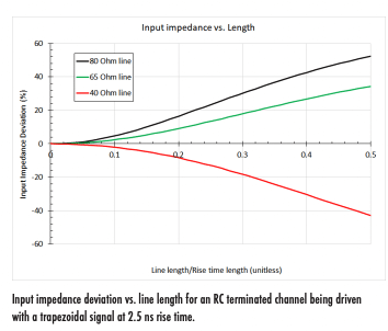
The example below shows results for a stripline embedded in a Dk = 4 medium with Df = 0.02. The characteristic impedance of the line was varied around the target impedance to determine the input impedance. For the moment we ignore copper losses and roughness (skin effect resistance).
The value on the x-axis is the line length divided by the rise time length (i.e., the length of time the signal travels during 10%-90% transition). In this example, we’ve assumed a signal rise time of 2.5 ns being driven into an RC terminated load.


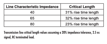
The critical length is found by drawing an intersection with the ±20% impedance deviation point for each curve. As we can see quite clearly, larger impedance deviations between the transmission line’s characteristic impedance and the target impedance allow for longer critical lengths.
If we extend the bandwidth requirement but keep the rise time constant, the critical length will decrease. This would account for any other digital input with additional parasitics, such as package/lead inductance.
In the above results, I have used the 3dB bandwidth limit for resistively terminated capacitive load to calculate the bandwidth. However, it should be noted that there will be signals that have no explicit relation between bandwidth and rise time. For example, in PAM-modulated signals, the bandwidth requirement is set by the receiver’s Nyquist frequency. With FM/QAM or other modulated RF signals carrying digital data, there is no rise time at all, so the input impedance must be used in all cases.
SUMMARY OF RESULTS
In conclusion, the above results illustrate 6 important conclusions about transmission line critical length rules in high-speed design:
• The critical length can be longer when the allowed impedance deviation is larger
• The critical length is shorter when the channel bandwidth is larger
• A critical length value depends on the following factors:
○ The line’s characteristic impedance ○ The line’s propagation constant (including losses)
○ The channel’s acceptable deviation from target impedance
○ The channel’s required bandwidth
Note that any critical length you calculate for an impedance controlled interface has no explicit dependence on the rise time of the signal.
Finally, because the analysis above works with single-ended interfaces, it is important to note that the analysis also works with differential interfaces. This works because the singleended impedance of the line in a differential pair is just the line’s odd-mode impedance, and there will be a slightly modified propagation constant. The calculation process shown above will not change.
WHEN CAN A CRITICAL LENGTH BE USED?
There is only a single practical situation in which the critical length rule can be used: in push-pull buses with fast rise time but no impedance specification. The most common example is SPI; the GPIOs on some ASICs and processors also exhibit this behavior. The I/O buffers on these parts also do not have fixed impedance.
In this case, you are basically using a critical length value as an estimate of when the bus needs to be slowed down with a series resistor, rather than attempting to hit some impedance specification. This is because single-ended push-pull buses like SPI and typical GPIOs do not have any impedance specification. In this case, slowing down the bus provides two functions:
•Reduces radiation on from I/Os
• Reduces intensity of reflections/ringing
The reduction in speed is helpful both for EMI and SI in moderate-speed single-ended buses. Adding series resistors is a simple option for SI and EMI that can also be modified without changing the design. If it is found that the series resistors are not needed, then they can be swapped in the assembly with 0 Ohm resistors and no other changes would be needed on the design.
WHAT IS THE CHANNEL BANDWIDTH IN THESE CALCULATIONS?
It is typical for someone to start using the classic -3 dB RC circuit bandwidth approach to qualify the channel bandwidth in terms of a rise time. In reality, this is not the correct bandwidth, including in terminated channels with a specific impedance requirement.
Deriving a relationship between the bandwidth and the rise time is much more complex than simply approximating an I/O as a charging/discharging RC circuit. This is another instance where the RC discharge approach is only appropriate in the simplest cases where the input can be approximated as a load capacitance within the channel’s bandwidth. In real systems, determining the bandwidth for use in a critical length calculation requires solving a complex transcendental equation, and that will be a topic left for a future article.
CONCLUSION
What is ironic is the fact that novice designers will use the critical length rule as an excuse to avoid calculating impedance, and yet correct use of the rule requires calculating at least 3 impedances. In addition, rise time also plays no role in determining a critical length. The fact that people can quantify the critical length in terms of a fraction of the rise time is a mere coincidence. The example above proves this.
In conclusion, I’ve taken to telling new designers and the purported experts in marketing departments to stop quoting this rule as gospel. The rule as described is only practically valid in very limited cases of fast push-pull interfaces with no impedance specification. A much easier approach is to just calculate and design to your interface’s target impedance, even in the case where your digital links would be considered “electrically short.”


