EXAMPLE OF AN EUT WHICH HAS FAILED RADIATED SUSCEPTIBILITY
As described in reference 1, the EUT was exposed to a radiated immunity test at a level of 20V/m.
The side which contained a vertical metal plate, with an approximately 0.3m x 0.3m dimension and which was electrically isolated from a metal baseplate failed at 12V/m and 300MHz.
On the other sides of the EUT, without the vertical plate, the EUT passed at 20V/m with a good margin. All four sides of the EUT contained cables and connectors with no significant differences in layout.
A 4mm gap existed between the vertical plate and the baseplate.
When this gap was closed with conductive adhesive, used as caulking, the EUT passed at 35V/m when the side of the EUT with the plate was irradiated.
TESTING A METAL PLATE WITH AND WITHOUT A GAP
As the results of the immunity test on the EUT seemed counterintuitive it was decided to test a metal plate with and without a gap in a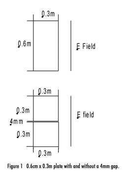 radiated immunity test setup. The coupling between a log/periodic biconical transmitting antenna with a frequency range of 20MHz to 1100GHz and a small electric field probe was measured. The tests were of the coupling without a metal plate, a metal plate having a 4mm gap in the center and a solid metal plate.
The metal plates, the orientation of the incident E field and the gap is shown in figure 1.
MEASUREMENT TEST SET UP
The tests were performed on a free space range with ferrite tiles and foam absorber on the poorly conducting ground between the two antennas, see reference 1. The distance between the log periodic biconical antenna and the metal plate was 1m.
The receiving antenna was a 4.2cm PCB antenna with two bow tie structures to make the antenna close to an isotropic antenna. A similar antenna was used as one of the antennas in a isotropic probe from 10kHz to 18GHz described in reference 2. The antenna in reference 2 had an isotropic deviation of maximum 0.9dB.
The antenna in the set up described here was connected to a differential high impedance, wide dynamic range RF/ IF detector with a frequency range of 10MHz to 1GHz. The dynamic range is 83dB+/- 1dB with a sensitivity of -76dB or better. The detector was connected to a preamplifier the output of which is connected to an A/D converter. The output of the A/D is connected to a fiber optic driver. The power supplies for the preamplifier, A/D and fiber driver was derived from a 9V battery.
As the only connection to the electronics was the non conductive fiber cable the potential for error introduced by a conductive cable was avoided.
TEST RESULTS
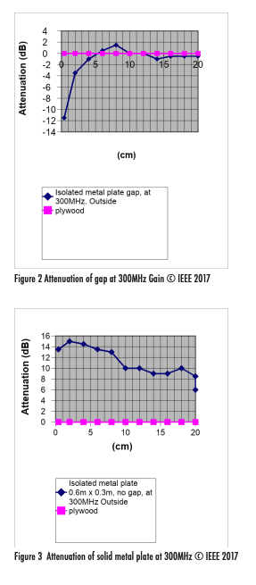
More detailed test results are provided in reference 1. A summary of the test results is that, though counter intuitive, the metal plate with a gap provides gain, as was seen in the immunity test on the EUT. This means that the coupling between the two antennas when a metal plate with a 4mm gap is introduced between the two antennas is higher than with the metal plate removed. For the 0.6m x 0.3m plate the gain is 12dB at 1cm distance, Figure 2, and for the 0.5m x 0.5m plate it is 8dB at 1cm, Figure 4.
N.B. a negative attenuation is gain.
The other very interesting result is that the plate with gap provides 0dB coupling at 10cm and 300MHz , figure 2 and 2dB attenuation at 20cm and 500MHz, figure 4.
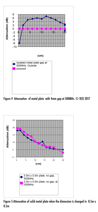
At 1cm the attenuation of the solid metal plate is not very high, only 14dB for the 0.6m x 0.3m at 300MHz.
For the 0.5m x 0.5m solid metal plate the attenuation at 1cm is 19dB at 300MHz and 17dB at 500MHz. The 0.5m x 0.5m attenuation at 25cm is 4dB at 300MHz and 5dB at 500MHz.
The 0.6m x 0.3m solid metal plate achieves very little attenuation at further distances from the plate, as low as 8dB at 20cm behind the plate and at 300MHz , figure 3.
USE OF AN ELECTROMAGNETIC ANALYSIS COMPUTER PROGRAM (COMPUTER ELECTROMAGNETICS, CEM, PROGRAM) TO FURTHER VALIDATE THE TEST RESULTS
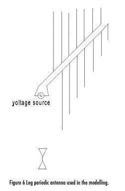 Figure 6 shows the thin wires used to model the transmitting antenna and the bow tie receiving antenna.
When current flows on these wires, due to an applied voltage, an E field is generated. Likewise with an E field incident on the wires a current flows. The computer program is used to analyses the radiated E field or the induced current. The Geometric Theory of Diffraction (GTD) formulation is a high frequency ray optics approach that has been extended to include diffraction effects from edges and corners. The MOM/ GTD program is very useful and accurate at computing the creeping wave around a cylinder and this computation has been compared to measurements in reference 3.
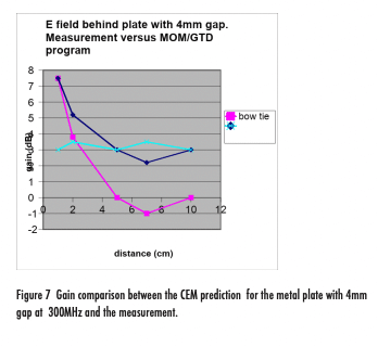
The computed attenuation of the metal plate with no gap, from reference 4, to the measured From reference 1 is:

A comparison of the CEM computed and measure coupling using a MOM/GTD program is shown in figure 7. The blue trace is the program and the red is the bow tie measurement, with only a 1dB variation between the two.
 CONCLUSIONS
The study has shown that placing a solid metal plate in front of a EUT to shield it in a radiated immunity/susceptibility test or to reduce the radiated emissions from a EUT, achieves minimal shielding and zero attenuation at a short distance behind the plate.
It has also been shown that a plate with a horizontal gap can show a gain in the vertically oriented field transmitted through the gap, even though the gap is only 4×10⁻³ lambda in width.
We also see that the width of the gap and the dimensions of the plate are relatively frequency independent. We see gain at 230MHz, 250MHz, 300MHz and 500MHz. For example the gain at 500MHz is 7dB ,at 230MHz it is 6dB and at 250MHz 9dB.
It was thought that the gain may be highest when the vertical dimension of the plate equals 0.5 lambda and this was not the case.
The vertical dimension of the plate at 0.6m is 0.6 lambda at 300MHz, 0.5 lambda at 250MHz and 1 lambda at 500MHz and the gain is virtually independent of this relationship.
The width of the gap was changed from 2mm to 3mm with very little change in gain.
The attenuation of the solid metal plate is very slightly affected by its dimension. For example a 0.6m x 0.3m plate has an attenuation of 8dB at 300MHz and a distance of 20cm whereas the 0.5m x 0.5m plate attenuation is 5db at 300MHz and a distance of 20cm.
The magnetic field with both the direct coupling and the coupling through the plate with aperture was also measured, with again a gain measured with the plate with aperture, although not as high as seen with the electric field coupling.
The measurements have been validated by a Computer Electromagnetics (CUT) program, described in reference 4, with a good correlation between measurements and computed results.
REFERENCES
Reference 1 : A study of Electric Field Behind Isolated Metal Plate in a Radiated Immunity Test Set Up. David Weston. EMC Consulting Inc. Merrickville, Ontario, Canada. IEEE Electromagnetic Compatibility magazine Volume 6, Number 2, 2nd Quarter 2017
Reference 2: An isotropic probe for radiated susceptibility measurements from 10kHz to 18GHz and 5V/m to 220V/m. David A. Weston May 2022
Reference 3: Comparison of Techniques for Prediction and Measurement of Antenna to Antenna Coupling on an Aircraft. 10th International Symposium on Electromagnetic Compatibility 2011. David A. Weston.
Reference 4: Use of an electromagnetic analysis computer program to further validate the study of the electric field behind an isolated metal plate in a radiated immunity Test Set up and the result of a literature search. David A. Weston ResearchGate January 2022.
