Introduction
This article will serve as an introduction to the topic. It is aimed at the people who have been told by their management, “You are now my EMC person. Go figure out what it is and how we must deal with it!” It will not be an all-encompassing treatment of the subject, but it will provide the reader with a start and some ideas of where to go for more information.
EMC stands for electromagnetic compatibility. You will see some people refer to EMC/EMI, but this is partially redundant. EMI (electromagnetic interference) is just a part of EMC. The two major parts of EMC are EMI and EMS (electromagnetic susceptibility) as it is called in the aerospace and military world and electromagnetic immunity (as it is called in the commercial world). Susceptibility and immunity are pretty much the same things, just called by different terms. Susceptibility is a measure of how a device reacts to various items in the electromagnetic environment and immunity is simply a demonstration of its failure to react to certain levels of these phenomena. Emissions are regulated in the commercial world in various ways and immunity for commercial products is regulated in certain countries and not at all in many others.
In the aerospace and military world, a common standard for emissions and susceptibility is MIL-STD-461G. Various tests and levels are called out for various services and products. In the commercial world, it depends on what product is being discussed, but for information technology equipment (ITE), broadcast receivers, and multimedia equipment, CISPR 32 provides limits for emissions and CISPR 35 provides tests and test levels for immunity. In the U.S., the FCC in Part 15 of its rules provides limits for emissions and does not mandate immunity for digital devices. In fact, the rules specifically state that a Part 15 device must accept any interference received. Countries that mandate immunity, on the other hand, require that products not suffer inference when tested to the levels called out in the applicable standards.
What Causes Electromagnetic Emissions in the First Place?
Various functions within a product may contribute to the generation of emissions. These emissions may be radiated from the product, typically as radio waves, or they may be conducted from the product via the power mains cable or other I/O cables connected to the product. Limits on the magnitude of these emissions are specified by regulatory bodies in many countries to protect licensed and unlicensed users of the radio spectrum from harmful interference.
Emissions from the product may be created by various means within the product. The two major means by which these may be generated are harmonics of intentional signals or parasitic emissions, which can come from improperly terminated transmission lines and the lengths of these lines.
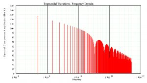
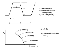
In the case of harmonics of clocks and other signals, these emissions will be related to the fundamental frequency and integral harmonics of these signals. Figure 1 shows the relationship of these signals. An envelope, which will not be exceeded in level by these signals is shown in Figure 2. They may not get up to this envelope in value, but they will not exceed it. The example shown is for a 50% duty cycle signal with a frequency of 500 MHz, a rise and fall time of .03 x 10^-9 seconds, a pulse width of .97 x 10^-9 seconds and an amplitude of 3.3 volts.

There are a couple of key things to note in Figure 1, including that the computed harmonics do not always rise to the envelope in Figure 2, but never exceed it. If you were to look at the signal (ideal) in both the time and frequency domains, it will look something like the following:

The fundamental of this 50% duty cycle signal actually falls above the first breakpoint in frequency when the envelope starts falling at -20 dB/decade of frequency. Above f2 the envelope falls off at -40 dB/decade of frequency. So, lowering the rise time of the signal moves this breakpoint to the left, decreasing the harmonics levels at higher frequencies faster. In reality, circuit designers are going to use the fastest products they can find, but the EMC engineer can always dream.
You may run into digital designers who say that 500 MHz isn’t very high. Just remember, 470 MHz is the bottom of the UHF television broadcast band, so 500 MHz is very definitely RF. It may not be high to a digital circuit designer, but it definitely is RF and will certainly radiate and cause interference to licensed services.
Why is this preceding information important? It gives the EMC engineer a tool for computing the frequencies that may come from the product, at least as harmonics of intentionally generated digital signals. It also gives a tool for computing the amplitudes of these signals. The next step, at least for computing the radiated or conducted emissions, will be to compute the coupling factor or factors, as a function of frequency. Or, if the measurements have already been performed, then troubleshooting to bring them into compliance may be the next thing on the agenda.
Another means by which RF energy can be created by a product is due to transmission lines that are not properly terminated. The frequency of these emissions will not necessarily be harmonically related to the frequency of the signal being sent down the transmission line, but, will instead, be related to the propagation velocity of the wave down the transmission line and its length. This termination may be designed into the product at either end of the transmission line and each has its advantages and disadvantages. Troubleshooting these emissions can take more detective work.
There are a number of ways that RF energy created by a product through its normal operation can generate and radiate unintentional emissions that can cause interference or simply failure to pass emissions limits. This paper will not go into detail on each as this would be way beyond the scope of a single paper, but things to consider are current loops, exit points from PWBs for cables, bypassing (all filters are not created equal and installation methods are critical), component layout, trace routing, chassis and packaging design, and “grounding”. Notice that I put quotation marks around grounding. Grounding in the EMC sense does not mean connection to earth ground. Ask yourself how this would be possible for a satellite in geosynchronous orbit around the earth. Obviously, it isn’t, and satellites typically have to meet far more stringent EMC requirements than your computer on your desk.
What is a Model for Interference?
There are three basic components in the interference model that must be considered.
There is a source. This may be a board, a complete device, or natural event. It generates the emission that is causing the problem.
There is a victim. This is the device (component, board, or full product) that suffers interference that causes whatever malfunction is being noted. This may be an unintended operation or a failure to operate on the part of the device suffering as a victim. Finally, there is a path for the interfering emission to travel from the source to the victim.
This may be a direct radiation path or a conducted path. It may fall under the control of the operator of the source, it may fall under the control of the operator of the victim, or a combination of both.
How Do I Fix an EMC Problem?
To quote a retired professor (Todd Hubing), “It depends.” What is the problem? Did your product fail an EMC test? Is it causing harmful interference to another device or service? Fix your product. This is especially important if you only control the source (in the case of emissions) or the victim (in the case of immunity testing). If you control both the source and victim, you may be able to alter the path and leave the source and/or victim alone.
Let’s assume that your product is failing an emissions test. This is not the best time to find out that you have an EMC problem as marketing probably wants to ship the product soon and you are being called the roadblock to shipping and are therefore the bad guy. Never mind that you have been telling the project team for a year that there are areas they need to address, and they have refused to make changes you’ve recommended. This is where a prime requirement to being an EMC engineer comes in—you must have a thick skin and stick to your guns. No data showing compliance, no shipment of product. Get to know the project lawyers well in advance, they likely will be on your side. You’ll spend long hours in the lab finding and fixing the problem(s). Oh, and your fixes must be manufacturable and, ideally, cheap (or even free). Sometimes these are, and sometimes they aren’t. Sometimes a product that passed in the lab last week or last month will have had a change made by a vendor as it was easier for them to make the part and your company’s specification wasn’t tight enough to prevent the change. Can you find this problem quickly and tell the program team how to fix it? Oh, and there are some problems that you will find repeatedly over a career as new designers come and go, creating job security for EMC engineers. So, from a personal point of view, these easy to find and fix problems aren’t all bad. At least not after you’ve found and fixed them a few times over the years. If you are new to the game it will take a bit longer.
Immunity
I haven’t discussed immunity as a separate issue much in this paper. The good news (at least on the commercial side of the discussion) is that immunity isn’t typically a major issue for designers and EMC engineers. Prior to immunity requirements being published for the first time about 30 years ago one major manufacturer only had internal specifications for electrostatic discharge and power line surges. Nothing else in their experience showed itself to be an issue. Some of the commercial immunity requirements are so low that the EMC engineer can tell the project designers 6 months in advance that he will run the test only because it is required, but not to worry as the product will pass. Or the company may have internal requirements for significantly higher test levels, in which case more attention must be paid to the test phenomena. ESD and surge testing, however, do not fall in the camp of serious concern. If a designer lives and works in an area where humidity levels are typically high, he probably doesn’t have much experience or worry about ESD failures. If, however, he lives and works in an area like the front range of Colorado or Washington D.C. where humidity levels can be very low, he likely will be a firm believer in ESD. Likewise for electrical surge, if the designer lives in an area where lightning storms are common surge is an issue. If not, no worries. However, the product must be sold and used in areas where these are common problems.
Then there are the immunity or susceptibility matters that must be considered to avoid problems like the U.S.S. Forrestal in the late 1960s. Susceptibility can be a serious matter. Three V/m may be adequate for some commercial environments, but the flight deck of an aircraft carrier is not one of those environments. Do a Google search and look for the video and discussion of what went wrong on the Forrestal to see what I mean.
Conclusion
EMC is a matter deserving of serious consideration. It may only be a matter of whether a product can ship on time, or it may be a matter of life and death. Learn about it, ask questions of people who are considered experts in the subject (I’ll give you my definition of “expert” some time), and read books and articles on the subject. Also, attend events where you can learn more about EMC by listening to papers, talking with vendors, and networking with “your fellow wizards”. You’ll find in many of those places that EMC folks (engineers and technicians) are EMC professionals first and employees of X, Y, or Z company second. They won’t disclose company secrets, but they will help you fight a common enemy—EMC issues.
Listed below are a few places where you can learn more about EMC.
- Noise Reduction Techniques In Electronic Systems, Second Edition, Henry W. Ott, John Wiley & Sons, 1988.
- This is a great book for learning more about EMC.
- Fields and Waves in Communication Electronics, Ramo, Whinnery and Van Duzer, John Wiley & Sons, 1965.
- I thought this was a lousy textbook when I was in college (maybe some bias there), but it is a fantastic reference book that I highly recommend you have.
- Introduction to Electromagnetic Compatibility, 2nd Edition, Clayton R. Paul, John Wiley & Sons, 2006.
- Clayton has passed away, much to the sorrow of those of us who knew him, but if I was limited to a single book on EMC, this is the one I would have. Not a simple, easy to read, treatment on the subject, but complete and comprehensive. I highly recommend this book.
- PCB Design for Real-World EMI Control, Bruce Archambeault and James Drewniak, Kluwer Academic Publishers, 2002/2004.
- The title says it all. It is limited to PCBs, but it is a great treatment on the subject, by two gentlemen who are well respected in the EMC world. Bruce is a past president of the IEEE EMC Society and has been around the block more than once.
There are plenty more books and papers that you can read and learn from. This is just a start, but for someone new to the EMC world this will be a great start.
Have fun and feel free to ask questions when you have some. I don’t say “if” because after 44 years I still have many.


