Introduction
EMI stands for electromagnetic interference. There are several methods of EMI transmission from the source to the victim. Two of them are radiated EMI and conducted EMI. Radiated EMI happens when an electrical device produces an RF signal that is picked up and causes unwanted effects. Conducted EMI is unintentional energy carried out of the source via signal cables or PCB traces. Common sources include antennas, RFICs, power supplies, and transmission lines.
Adverse effects of EMI include passing or failing regulatory emissions tests and neighboring antenna sensitivity. Common solutions include shield coverings, EMI absorbing materials, ferrite chokes, and grounding clips. The disadvantages of these solutions include cost, space, and increased time on labor and assembly.
Over the past 40 years, EMC requirements have evolved. In 1985, Cray made the world’s most powerful supercomputer. Today, that computing power resides in today’s smartphones, tablets, and portable computers. In 1985, system-level shielding for a typical desktop computer was sufficient. Today, that computing power resides in your hand. External cables have been cut and radiating structures, like antennas, have been added. In 1985, we did not see much need for component-level shielding for interconnects. Today, many devices require fully shielded solutions to isolate radiating sub-sections from one another.
CABLE ASSEMBLIES
How do cable assemblies specifically affect EMI? To answer that question, we will need to investigate the components of the cable assembly, namely the cable construction and the connectors on the ends. There are two common types of unshielded cables, discrete wire and twisted pair. Since neither has shielding around the conductors, the EMI radiation is unhindered.
Shielded cables mitigate EMI by wrapping a shield around the conductors. Two common examples are Micro-Coaxial Cable and shielded twisted pair. Shielding the cable helps with direct radiated emissions from the cable, but mismatches in differential pairs also exacerbate EMI. This is referred to as intrapair skew.
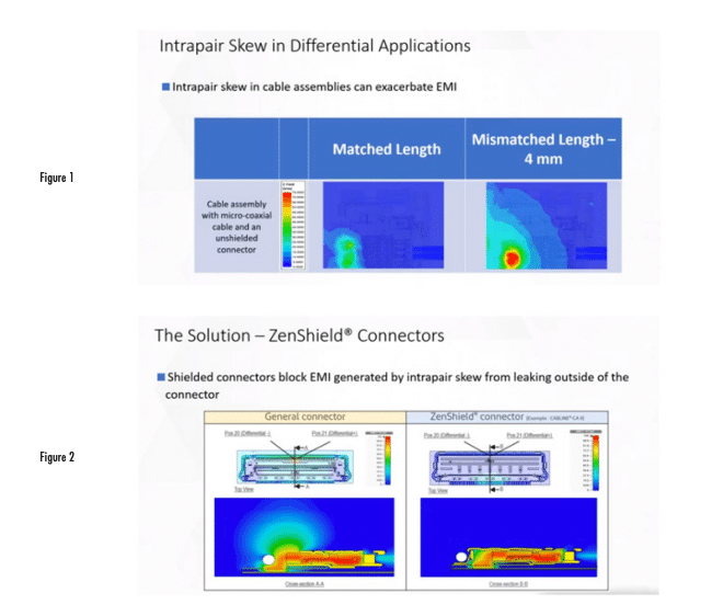
Intrapair skew is the timing difference between the positive and negative signal lines within a differential pair. It is caused by mismatches in electrical length or unequal propagation delays. Shown in Figure 1 are E-field plots of a cable assembly. The left has a match differential pair and the right has a four millimeter mismatch within the pair. The length mismatch causes intrapair skew and a much larger electric field.
ZENSHIELD CONNECTOR
What is the solution? Using a fully-shielded connector. Not all connectors that have a shell or shield will work. The shield needs to completely surround the signal contacts in order to contain the electric fields. At I-PEX, this type of connector is called a ZenShield connector. A connector is only rated as ZenShield if it has the following three characteristics. One, the entire connector is covered by 360 degree shielding for both the plug and the receptacle. Two, the shield-to-shield interface between the plug and receptacle is effectively connected at multiple points. Three, the connector shield-to-board interface is properly grounded at multiple points on the board.
Shielded connectors block EMI generated by intrapair skew from leaking outside of the connector. As you can see on the left of Figure 2, EMI radiates freely without the aid of a shield. The shielded connector on the right blocks unwanted radiation from the signal contacts. We simulated the effect of length mismatch within a differential pair on EMI. We also compared the use of unshielded connectors in one assembly and shielded connectors in another assembly. We ran several side by-side comparisons of shielded versus unshielded connectors. We compared matched lengths, a slight mismatch of one millimeter, and a larger mismatch of four millimeters.

The simulated effective intrapair skew values for the three conditions are as follows. Matched length, 0.2 picoseconds. Mismatched length of one millimeter, 3.5 picoseconds. And mismatched length of four millimeters of 16.6 picoseconds. As we can see from the mode conversion simulation, the more mismatches we have, the worse the mode conversion results. This is expected as the differential pair is no longer balanced.
To illustrate the E-fields, we looked at the top view, 0.5 millimeters above the connector. Here we see larger E-fields as the mismatch increases. However, the shielded connector in the bottom row has significantly less emissions compared to the unshielded connector in the top row. We also looked at the E-fields from the side view or cross-section of the connector. You can see that in the shielded connector, all of the E-fields remain contained within the connector. Whereas in the unshielded connector, some of the E-fields leak from the area where the signal contact is soldered to the PCD. This shows that shielded connectors provide an additional margin for assembly tolerances as EMI from intrapair skew can be mitigated.
Conclusion
I-PEX offers various types of fully shielded wire-to-board connectors. We offer vertical or horizontal options along with multiple pin counts and pitches. ZenShield connectors give board designers more flexibility for designing the board by allowing the connectors to be placed close to sensitive subsystems, such as transmit receive antennas commonly found in high-performance wireless communication systems. I-PEX also provides ZenShield connectors for other applications like antennas or boardto-board and FFC-to-board connections. For more information, please visit https://www.i-pex.com/.
References
1. https://www.i-pex.com


