Philip Keebler, Kermit Phipps, Frank Sharp, EPRI Lighting Laboratory
For years, lighting systems have been operating as stand-alone loads without the use of sophisticated lighting controls for energy savings in all types of facilities—residential, commercial, and industrial. Utilities and end users viewed lighting controls in the past as, luxury, systems that were used only when mood or special effects lighting was needed. Although two industries—broadcast and theatrics—have relied on dimmable lighting and basic lighting control systems for years as a part of their stage and set lighting, systems were very simple and traditionally dimmed only incandescent lamps. Other types of light sources were either not dimmable or did not provide the color performance needed for television cameras or live audiences.
Today, however, the need to provide dimmable lighting systems in more types of customer spaces is different today. With the help of lighting designers and energy researchers, end users are finding more applications for dimmable light sources paired with more sophisticated lighting control systems. Dimming is no longer limited to incandescent and electronic fluorescent systems. Dimmable lighting device designs are finding more application in electronic high-intensity discharge (HID), induction, and LED devices and other advanced lighting systems. Lighting researchers are discovering more ways to optimize lighting levels in various spaces by incorporating the use of dimmable light sources and lighting control systems. Commercial facilities are probing deeper into new applications for dimmable light sources and lighting control systems in efforts to improve energy savings. Some installations are even making better use of outdoor light as they strive to harvest as much daylight as possible to offset their energy usage for lighting systems. Utilities are experimenting with various dimmable light sources and various types of lighting control systems through EPRI demonstration and other projects while examining customer perceptions, how much energy savings can be achieved without interrupting the customers’ business, and verification of savings before rebates and incentives are issued.
The federal government and other supporters of green initiatives are putting pressure on building designers, utilities, and end users to improve energy savings in various types of facilities. Lighting is one of those load types where energy savings is very achievable, and if implemented correctly, can be employed without introducing lighting and power quality problems into customer facilities. With lighting representing as much as 23% of the grid load, with many customer spaces characteristic of over illuminated conditions, and, to utilize daylight to offset the need for electric lighting, there is much opportunity to reduce energy usage and demand with the use of dimmable light sources and lighting control systems.
Utilities and customers alike who do engage in using dimmable light sources and lighting control systems do so today with many reservations and concerns. They are aware of some problems that have occurred when pairing dimmable light sources with lighting control systems in common everyday electrical environments. Several of these problems resulted from compromised lighting device and controls performance caused by poor power quality (PQ) and poor electromagnetic compatibility (EMC).
Utilities and customers expect new systems to work well together and to function properly in their expected electrical environments regardless of facility type. Lighting control systems should function properly regardless of what other neighboring loads are used in a facility. When compatibility problems occur with lighting devices and/or control systems, even lighting problems can grossly affect the customer’s business operations regardless of which type of lighting device—fluorescent, HID, or LED—is used. Some problems are severe enough to cause facility shutdown until action can be taken to disable the lighting control system. These problems can result in lost downtime and re-installation costs that can add up to the thousands of dollars.
The complexity of these systems and the demand for complete functionality warrants the need for improving the compatibility between lighting devices and control systems and their electrical environments. Utilities and end users must endure increased pressure to improve building performance and reduce lighting energy costs while controlling facility budgets.
This article seeks out to describe the importance of achieving compatibility between lighting devices and control systems and the electrical environment while understanding PQ and EMC barriers that typically occur with lighting
devices and control systems. Past EPRI research in the area of system compatibility has been applied to many types of electronic lighting devices. The application of EPRI’s system compatibility concept can be used for lighting control systems not only to document energy, emissions and immunity performance, but
to harden lighting controls systems and to continue hardening electronic lighting devices.
COMPATIBILITY PROBLEMS WITH LIGHTING CONTROLS
Regardless of the type of communication link used to communicate with controllable light sources, their networks spread out across a facility and penetrating the electrical and electromagnetic environment.
Lighting control systems may use various types of communication links in essentially all types of lighting devices—fluorescent, HID, and LED:
• Hard-wired, low-voltage, 0 – 10 volt DC, analog control
• Line-side, line-voltage control
• Line-side, low-voltage, three-wire control
• Wireless (e.g., Zigbee)
• Line-side, power-line carrier control
• Hard-wired, low-voltage, DALI (Digitally Addressable Lighting Interface) control.
Each method of communication requires dedicated electronic circuits inside the lighting device. Penetration of the communications circuit inside the lighting device further exposes the other electronics inside the lighting device to malfunction and upset. For example, when an electrical fast transient (EFT) is coupled into a lighting control circuit, this voltage anomaly is carried to the electronic inside the lighting device.
The electrical and electromagnetic environment can both interact with each of these communication systems to cause any of the following compatibility problems, all of which have been witnessed in the field by EPRI and various end users.
• Inability to turn light source on when an ‘on’ command is sent
• Inability to turn light source off when an ‘off’ command is sent
• Inability to dim light source up (increase intensity) when a ‘dim up’ command is sent
• Inability to dim light source down (decrease intensity) when a ‘dim down’ command is sent
• Complete malfunction of lighting controller (light sources will not respond to any end-user initiated commands)
• Unstable operation of light sources (flickering lamps, random turn ‘on’, random turn ‘off’, etc.)
• Complete failure of lighting controller
The sources of electrical and electromagnetic disturbances that can affect lighting controls include many types of industry defined waveform disturbances and random waveform disturbances that extend from a few tens of hertz up to hundreds of megahertz. Such disturbances can be generated from a wide variety of end-use equipment and operation of electrical equipment inside a residential, commercial or industrial facility. Although the number of disturbance sources is not as many in residential settings as in commercial and industrial settings, the types of equipment that can generate these disturbances in residential settings is increasing as end users acquire more non-linear electronic loads like high-definition televisions and electronically controlled appliances including those with adjustable speed drives (ASDs). Example sources include the following
• Transients generated by the switching ‘on’ and ‘off’ of large loads such as heat pumps, refrigerators, ovens, pumps, washers, dryers, etc., and even induction cooking appliances
• Conducted noise generated on the power line by electronic loads including electronic lighting devices using electronic ballasts and by failing power supplies in computers, audio and video equipment, and in gaming equipment
• Voltage notching generated by the operation of highly-inductive loads (appliances that contain ASDs and motors)
• Voltage distortion generated by increasing penetration levels of electronic appliances that inject harmonic currents into the customer wiring system
• Electrical noise on the branch circuits generated by radiated emissions from radio transmitters, wireless devices, etc.
• Transients (surges) generated by thunderstorms and lightning strikes and also transients picked up by automatic lawn sprinkler systems
Moreover, with the use of lighting controllers there is another opportunity for control system upset caused by radiated transients and high-frequency radiated emissions that can also be coupled onto any one of the hard-wired communications links. The thousands of feet, or miles (in some cases), of control cable is exposed to electric fields generated by transients and emissions and may cause distortion or corruption of control signals. In almost all cases, these cables are either not shielded or contain the very minimum amount of cable shielding due to the added expense of shielded cables.
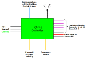
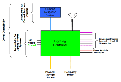
Figure 1 illustrates the basic concept of the primary ports commonly used on a lighting controller and how they can act as entries for electrical and electromagnetic disturbances. The line input port is a line-voltage power port usually rated at 120 volts AC but may also be rated at a universal voltage (e.g., 120 to 277 Vac) or higher AC line voltage (e.g., 230 Vac) in European applications. The dimming control ports (four shown in Figure 1, other controllers may have fewer or more of these ports) are low-voltage ports and usually rated for up to 10 volts DC. These ports deliver a very small power to the dimming control circuit of a dimmable lighting device. Most lighting controllers have two or more sensor ports which may be used to support one or a series of remote sensors located somewhere out in a facility at a considerable distance from the controller. In Figure 1, these are the photocell (daylight sensor) port and the occupancy sensor port. To operate these sensors, a separate DC supply voltage is required—usually 12, 15, or 24 volts DC. The communications port is also a low-voltage port, but for network signals where multiple conductors which can be Ethernet, RS-232, or RS-485 are used. The wireless port is one that is showing up more on lighting controllers. This port and the network port(s) may be of an open (e.g., Zigbee) or closed architecture.
Figure 1. Example of lighting control system with multiple circuits.
EXPOSURE TO ELECTRICAL AND ELECTROMAGNETIC DISTURBANCES
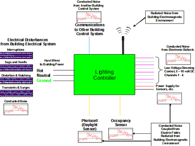
A lighting controller installed in a facility, whether the facility is a residential, commercial, or industrial one, is subject to the same exposure to electrical and electromagnetic disturbances as any other piece of networked electronic equipment (e.g. a computer) which also uses control and signals ports and control cables. Figure 2 illustrates several scenarios where disturbances can impinge upon the hard-wired and wireless ports of any lighting controller used to control any lighting device—fluorescent, HID, or LED. Each port essentially has some susceptibility to these disturbances, and this susceptibility will, at some level and frequency, cause the lighting controller to malfunction, be upset, or be damaged. The question is “How susceptible are lighting controllers to the electrical and electromagnetic disturbances that commonly occur in the customer’s electrical (facility) environment?” The only way to definitively determine their susceptibility is to test them in a controlled laboratory environment capable of generating industry standardized, random, and field documented disturbances.
Figure 2. Electrical and electromagnetic disturbances that can impinge upon a lighting controller.
CROSS-REFERENCING DISTURBANCES AND FAILURES WITH LIGHTING CONTROL SYSTEMS
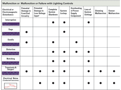
Because of the nature of lighting control systems and the electrical and electromagnetic disturbances that occur in environments where multi-port systems must live, there is significant opportunity to improve their performance. Performance improvements are based on which disturbances impact which part of a lighting control system and the severity of the malfunction or upset. Obviously, any disturbance that causes permanent damage must be resolved without delay. Table 1 lists various types of malfunctions and failures that may occur with lighting controls. Each one of these has occurred in the field as reported by utilities, various manufacturers and end users. Some of these may be resolved with a system reset and some require hardware replacement. Others may require a circuit enhancement in the lighting controller to improve the immunity of the system to a specific disturbance. Regardless, these present problems to the end user that will likely interrupt the nature of their business and function of the lighting control system. In some situations, the interruption will present safety issues to the facility or its occupants as well.
Table 1. Cross-reference between electrical and electromagnetic disturbances and malfunctions or failures of lighting control systems.
Discussions with manufacturers of lighting controls and end users who have installed them in the past several years have revealed that the nature of compatibility problems as listed in Table 1. Compatibility problems are indeed occurring and increasing with some communication methods. The good news is that the performance of lighting control systems can be improved with the application of EPRI’s System Compatibility concept. The increase in compatibility problems among lighting control systems can be attributed to four causes: 1) the increased complexity of lighting control systems (i.e., more use of electronic microcircuits and more use of low-voltage ports for network, control and signal functions, 2) the increased complexity of the electrical and electromagnetic environments where systems are installed, 3) the increased frequency of use (i.e., end users are using them more often in applications where lighting control is needed or required to meet certain specific energy savings goals) of lighting control systems, and 4) the increased development of new electronic lighting devices and their increased use.
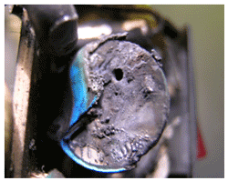
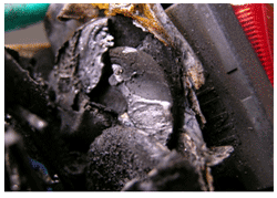
One area where failures have increased is in the protection of the AC power port against voltage surges. In visually inspecting MOV failures in lighting controls, thermal runaway has been increasingly observed. Thermal runaway may occur if an MOV with too low of a maximum allowable voltage is applied in lighting control equipment in efforts to provide protection against voltage surges. In such a case, an MOV’s exposure to a long-term overvoltage may be higher than the MOV’s maximum allowable voltage, and thermal runaway of the MOV may occur without blowing the line fuse. Figures 4 and 5 show two examples of MOVs in lighting controllers, which failed as a result of thermal runaway. In both examples, the MOV ignited and a significant part of the MOV material was burned by the fire caused by its own thermal runaway. The fire from the MOV damaged other nearby electronic components and the enclosure for the lighting controller. If investigators discover this type of MOV failure surrounded by other burned insulation and electronic components, then thermal runaway can be suspected. These susceptibilities, or weak links in the design of these lighting controllers, can be identified through compatibility analysis and testing at the EPRI Lighting Laboratory.
Figure 3. MOV failure caused by thermal runaway and internal equipment fire in a lighting controller.
Figure 4. MOV failure caused by thermal runaway and internal equipment fire in another lighting controller.
SYSTEM COMPATIBILITY AND POWER QUALITY
What is a power quality problem? Imagine this. . . . The fluorescent lights connected to a lighting controller in a manufacturing facility blink, indicating that the voltage has briefly dipped. A split second later, the high-intensity discharge (HID) lights drop out, adjustable-speed drives that control process motors trip, and scrap material gathers on the floor of the now dimly lit manufacturing facility. A few minutes later, the indoor LED lighting devices begin to oscillate, causing the illumination to rise and fall slowly. Or this. . . . Lightning strikes near a telemarketing facility. The uninterruptible power supplies connected to the computer systems switch on, but some of the computers lock up, disrupting data processing and vaporizing data. The light from the overhead dimmable fluorescent lighting system fades as about one-third of the fixtures go out. Or perhaps you don’t have to imagine if you use magnetic HID ballasts with metal halide lamps and have been left in the dark for 15 to 20 minutes before the lamps cool down enough to restrike. Imagine this type of problem when your lights are connected to a lighting controller. The lighting controller is in full command of the lights, but the lights cannot be turned back on because the controller already says they are on.
Every year, problems with electricity and electrical equipment cost U.S. companies billions of dollars in scrap material, down time, damaged data, and delayed orders. Every year, electric utilities produce and deliver almost two billion cycles of electricity. If just a few of those cycles are disturbed, computers in commercial offices may crash, industrial equipment may shut down, and entire processes may grind to a halt. Moreover, equipment in one facility may cause other equipment in the same facility or in a neighboring facility to malfunction, even when the quality of delivered power is perfect. With lighting controls, which are embedded within a facility’s electrical system, these problems become even more compounded. Each wired port on a lighting controller is a “door” for an electrical or electromagnetic disturbance to enter the controller. With facilities becoming more cluttered with electronic equipment, the frequency of occurrence for disturbances, their disturbance levels (both low and high frequency) are increasing. As buildings become more intelligent, more compatibility problems will surface and render equipment inoperable.
APPLYING POWER QUALITY AND COMPATIBILITY TO LIGHTING CONTROLS
Power quality is the concept of powering and grounding electronic equipment in a manner that is suitable to the operation of that equipment as defined by the IEEE Standard 1100, The Emerald Book. (Early EPRI research in the area of system compatibility provided many contributions to this publication.) Power quality is a concept that was developed to study and improve the quality of electric power as it is generated, transmitted, and distributed to utility customers and consumers by electrical and electronic equipment.
Manufacturers and consumers often misapply the definition of power quality. Without even a basic understanding of power quality, they often think of quality power as power that contains absolutely no imperfections. Mistakenly, they apply the same thinking to lighting controllers as well as electronic lighting devices. Similarly, an electrical engineer unfamiliar with the power quality concept may think of quality power with a ‘perfect sine wave’ with no irregular waveshapes or distortion whatsoever and a data string as a perfect stream of zeroes and ones. Both of these are incorrect perceptions of power quality as the input power to lighting controllers and the data they must deliver and receive contain artifacts resulting from the occurrence of electrical and electromagnetic disturbances in customer facilities.
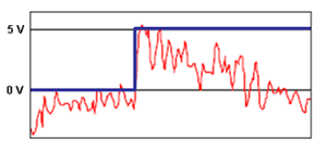
Figure 5 illustrates a rising data pulse captured on a port of a lighting controller that receives a command from a daylighting sensor. This pulse is supposed to be a digital zero traversing to a digital one (e.g., 0 volts traversing to 5 volts) in an attempt to activate dimming of a bank of dimmable lighting fixtures connected to one of the dimming ports of a lighting controller. The pulse contains high-frequency conducted noise. This noise has entered the control cable that runs from the controller to the daylight sensor with timing and amplitude characteristics limits set by the manufacturer. The cable was shielded, but the shielding material failed. The shield did not reduce the noise current in the shield that resulted from the in flux of a high-frequency radiated electric field present in the building. The electric field was generated by a set of input power cables running from an electrical panel to the input of a set of adjustable speed drives.
Because these emissions are associated with the electrical branch circuit inside a building. The operation of the ASDs (i.e., a non-linear load), created the problem on the branch circuit. This is considered to be a system compatibility problem. The quality of the voltage on this circuit is corrupted by the presence of these high-frequency emissions.
Because the lighting controller is susceptible to these emissions, the controller is deemed to have a compatibility problem with its common everyday electrical environment. One might ask, are these emissions really common in a commercial or industrial electrical environment where the compatibility problem occurred? All ASDs produce some conducted emissions on their input circuitry which travel out of the ASD up the branch circuit. The emissions levels among ASDs do vary with ASD manufacturer and model as well as the impedance and length of the branch circuit and some other variables. These emissions were being coupled into the daylight sensor control cable as the cable was run in parallel and too close to the branch circuit powering the ASD. One could remove the problematic lighting controller and replace it with one that had the exact same design (i.e., same input power requirements, same types of lighting control channels with the same daylighting control functions) and this problem may never have occurred.
The immunity of the daylight sensor input when used with a specific control cable and daylight sensor will vary among lighting controller. However, in this case the problematic lighting controller has an immunity low enough to allow this problem to occur while other controllers had a higher immunity to these emissions at these frequencies.
The lighting controller was rendered inoperable as a result of this compatibility problem and was removed from the facility. This indicates a couple of major points for concern: 1) the shielding of the control cable was insufficient to protect the data signal inside the cable from the radiated electric field and 2) the port of the lighting controller could not filter out this noise in the data signal and caused the controller to lockup.
Figure 5. A rising data pulse (going from zero to one) corrupted with conducted noise.
In order to better understand power quality and system compatibility and how it can be applied to the characterization of end-use equipment like lighting controls, EPRI has developed a detailed concept called system compatibility which can be applied to any electronic device including lighting controls. A series of system compatibility tests can be applied to a lighting controller to determine its energy, emissions, and immunity performance for each power and signal port and the product as a whole.
An EPRI test procedure exists which allows each type of electrical and electromagnetic disturbance to be applied to the proper ports of a lighting control. The low-frequency disturbances are derived from definitions for each type of voltage variation and disturbance that occurs on the power system and inside customer facilities. These definitions, which are now standardized and part of an IEEE standard 1159-1995 (R2001), IEEE Recommended Practice for Monitoring Electric Power Quality, were in part developed through actual power quality studies conducted at EPRI on various power systems across the United States in the last 15 to 20 years. Through having developed a thorough understanding of power quality, power system engineers and system compatibility engineers (engineers who study the compatibility between the power system and end-use electrical and electronic equipment) have been able to determine how equipment responds to each type of variation and disturbance.
WHAT IS SYSTEM COMPATIBILITY?
When equipment and appliances get along in the same electrical environment, they are said to be in a state of system compatibility. System compatibility is defined as the ability of a device, equipment or system, generally a load, to function satisfactorily with respect to its power-supply electrical environment without introducing intolerable electrical disturbances to anything in that environment. However, in today’s complex and diverse electrical environment, achieving system compatibility is often a steep challenge for any product designer, especially for multiport systems like lighting controllers where compatibility must be applied to each port. For example, modern industrial processes rely on sophisticated electronics for precise and continuous process control, and malfunction and upset of these electronics can jeopardize process reliability. Industrial plants that rely on process reliability also rely on quality lighting control systems. When these plants apply demand response, utilities will be relying on reliable communication and operation of lighting control systems to shave load when required to ensure power system stability. Commercial facilities are characteristic of the same types of disturbances and operation of disturbance-generating loads like ASDs more commonly used in heating, air-conditioning, and ventilation systems. An increasing number of lighting controllers rely on feedback from daylighting sensors spread throughout a facility to determine what appropriate levels of light are needed in task areas where sensors (and windows) are located.
There is more to the quality of a lighting system than measuring the photometrics of the light. A quality lighting system includes the following, some of which are directly influenced by a lighting controller. These general performance requirements are not only important to lighting controllers but are also important to demand response activities. Demand response requests will utilize lighting controllers to initiate commands to make adjustments in lighting loads by turning dimmable lighting devices ‘on’ or ‘off’ or change dimming levels.
If disruption to a lighting controller occurs in a demand response application, the controller may or may not initiate the request properly. Moreover, the controller (or a separate monitoring device) may or may not be able to verify that the request was actually carried out. A situation where a request called for the dimming of certain lights may actually have occurred, but verification of that request indicated otherwise. The converse problem may also occur. Regardless, compatibility problems with lighting controllers may leave the utility (and the customer) in a state of unknown when it comes to load reduction and energy savings.
Photometry
Compatibility can also impact the photometrics of a lighting system. In lighting control applications, it is important that a dimmable lighting device response as intended to a lighting control command. A compatibility problem may cause a lighting control system to render one of the following problems to a dimmable lighting device.
• Providing an unstable arc (discharge) inside an HID lamp at some dimming level because the wrong dimming level was reached
• Providing a sable DC current for an LED fixture (a driver function)
• Providing an incorrect amount of foot-candles targeted toward an area where the light is needed
• Providing an incorrect color of light where light of a different color is needed
• Making an inappropriate adjustment (too low or too high) light levels based on how much ambient light enters a room or space
Safety, Compatibility, and Power Quality
Safety must be the first priority in any facility regardless of the business activity. Reliable and compatible lighting systems play a vital role in maintaining safety. Lighting devices and lighting control systems which are not compatible with the electrical environment will increase the risk of an accident occurring. Aside from increased efficiency, one of the primary benefits of using electronics in lighting devices is to enhance safety-related performance. However, if the electronic ballast (or driver) is not compatible with the electrical environment, then safety-related performance will likely be compromised. Listed below are some examples of why lighting is critical to safety.
- Keeping the lights on when they are needed
Minimizing the number of lamp drop outs - Maintaining as much lumen output for the life of the lamp as possible – called lumen depreciation – to avoid light levels that are too low before lamps reach the end of their expected life
- Avoiding lamp flicker as the load inside and outside a facility changes – flickering lamps may cause rotating machinery to appear ‘standing still’
Compatibility, Reliability and Economics
Electronic lighting devices and lighting control systems require a capital investment. To reap the return on investment (ROI), projected costs must be maintained within their estimate to avoid stretching out the pay back period. Pay back periods for lighting upgrades usually run from about one year to as long as three to four years depending on a variety of factors. Utilization of lighting controls typically shortens the pay back period. Listed below are examples of some cost-related expectations:
• Maintaining efficacy (efficiency) for the expected life of the ballast and lamp or the driver and LED
• Achieving enough lamp and ballast or LED and driver reliability to achieve a return on the investment that the customer has made in purchasing and installing the modern lighting system
• Ensuring that the lighting control system of an electronic ballast or electronic driver remains fully operational over the life of the ballast/driver so that lighting load can be adjusted according to customer needs or the utility’s desire to reduce peak load in future demand response applications
Each of the above categories involves the use of a lighting control. Considering a few examples, the first two categories in the above list are centered around the lamp and the fixture. The next two bullets are related to the performance of the lamp-ballast or LED-driver system. This performance also depends on how the lamp-ballast or LED-driver system responds to variations or disturbances in the AC line voltage powering the lighting system.
EPRI research indicates that LED-driver systems combined with lighting controls may be more susceptible to common everyday electrical and electromagnetic disturbances than lamp-ballast systems combined with the same controls. When the customer makes an investment to purchase and install a modern lighting system such as one that uses high-frequency HID or LEDs, that customer expects the system to operate reliably. Reliable operation should last for at least a minimum of the warranty period. The warranty period offered by the lamp, ballast and fixture manufacturer will likely be different. The lighting specifier, retrofitter, and/or installer can help one understand the nature and design of warranties and their periods. A severe electrical event, such as a near lightning strike, high voltage distortion, or a larger than expected number of sags may occur during the warranty period. Manufacturers may not honor the warranty if extreme events occur. Power-line monitoring of the lighting branch circuit, a facility power quality audit, and/or a forensic analysis on a failed ballast (or driver) or lighting controller by EPRI may reveal the cause of an early failure. If the facility environment reaches a high ambient temperature, the lamp and ballast (or LEDs and driver) life may be shortened possibly causing premature failure.
WHY APPLY SYSTEM COMPATIBILITY TO LIGHTING SYSTEMS?
Traditionally, lighting systems from the days of Thomas Edison were of the incandescent type. No energy conversion device was needed between the power system and the lamp, and no lighting controls were used. This does not mean that disturbances in the power system did not affect incandescent lamps. This simply means that the incandescent lamp is under direct influence of disturbances that occur on the power system. Compatibility tests conducted on incandescent lamps have shown that the reliability of lamp filaments are affected by disturbances such as voltage sags, voltage swells, and voltage surges. With respect to the end user, a change in illumination is usually noticeable with these disturbances until the lamp fails to produce light when the filament is severed. With lighting control systems, failures and malfunctions in lamps are also possible and can actually be initiated by malfunctions in lighting controllers.
Early fluorescent-based lighting systems were developed by leading manufacturers soon became popular lighting products for end users of all types. These systems through the use of a magnetic ballast were connected to a fluorescent lamp. The purpose of a ballast is to produce enough energy to ignite a lamp and then control its illumination through either voltage or current control.
In magnetic fluorescent lighting systems, the magnetic ballast is a simple core-and-coil type of device with no sophisticated electronic components for controlling lamp performance. These ballasts also respond to various types of steady-state and transient power-line disturbances. With vary little voltage regulation built into a magnetic ballast, the ballast will allow an increase in illumination with an overvoltage or a voltage swell and a decrease in illumination with a voltage sag. However, the core and coil of a magnetic ballast system have the distinct advantage of having a more-than-acceptable immunity to voltage surges.
Although this type of immunity helps to increase ballast reliability, end users often complain about issues other than ballast failures such as noticeable variations in light fluctuations. These fluctuations in light output are called lamp flicker. All types of lamps and lamp-ballast systems have their own characteristic response to various types of voltage fluctuations—the type of line-side disturbance that causes lamp flicker.
Lamps and lamp-ballast systems may act as amplifiers of voltage fluctuations or they may act as attenuators to fluctuations. Each component of the lamp-ballast system plays a different role in determining the extent to which the lamp-ballast system acts as an amplifier or attenuator of fluctuations. When acting as an amplifier, a small fluctuation incident on the AC input of a lamp-ballast system, for example, will result in a large change in light output. The same is true for lighting controllers—disturbances initiated at the line input may find their way through the lighting controller and into the signal that controls the light output of electronic ballasts.
With respect to end users, each human eye also has a distinct frequency response to lamp flicker. Some people can notice a lamp flickering when others cannot. Some will indicate that what may be defined by some as a mild lamp flicker will actually cause severe headaches, thus preventing users from functioning in a work environment. This is because their perception to lamp flicker varies from person to person. Lamp flicker studies have been conducted on many types of incandescent and fluorescent lamps and ballasts with the results varying among lamp and ballast models as expected. As more lighting systems become electronic, lamp flicker studies will continue to gain more attention, especially for systems operating at higher lamp wattages such as HID lamps where a small amount of flicker in a fluorescent lamp may not be very noticeable as compared to that same amount of flicker in an HID lamp that may be more noticeable.
While the human perception-related performance issues in lighting systems can gain much attention from utility customers, professionals in the lighting industry traditionally focus on lamp and ballast performance and reliability. These professional groups include architects, lighting specifiers, facility electrical designers, lighting engineers, and lamp and ballast designers. Each of these groups strives to provide acceptable lighting systems for their customers that meet their expectations in terms of lamp and ballast performance and reliability. Each strive to 1) provide lighting systems that maintain acceptable light output for the majority of the life of the lighting system and 2) provide lighting systems that function at an acceptable level for at least the term of the product warranty.
Manufacturers of electronic fluorescent ballasts learned about performance and reliability the hard way. Many of them did not understand the whole-system performance: how to design a high-frequency inverter type of power supply, populate a printed circuit board with components rated for an elevated operating temperature, solder them to the board, place that board inside a metal can, pour hot potting material over the circuit, and install it into a lighting fixture. Many lessons regarding circuit design, component reliability, soldering, specifications, and potting were learned. With some knowledge about ballast reliability and the warranty term, many manufacturers did not have enough data to reasonably design and specify their warranty programs. Both manufacturers and end users experienced significant financial losses from poor lamp and ballast reliability.
Many have asked how system compatibility testing could have prevented much of these financial losses. At the time when the first electronic fluorescent ballasts were being designed, component manufacturers were also not familiar with applying their devices in ballasts. Component engineering combined with a temperature-based compatibility study might have helped reduce the number of failures cause by the overheating of electronic components. Compatibility testing would not have had much of an effect on manufacturing defects including soldering. However, during many of the forensic studies that were conducted on failed electronic fluorescent ballasts, it was found that disturbances which would not normally affect a well-designed electronic ballast would have a much more negative effect on the performance and reliability of a ballast with design problems. Disturbances such as voltage transients and voltage sags were found to cause premature failure of ballast circuits and the component lead-to-solder joint junction. Compatibility testing on such samples prior to production would have resulted in the identification of ballast reliability issues prior to the installation of thousands of ballasts that eventually failed when powered in a normal electrical environment.
For these reasons, manufacturers and end users of electronic ballasts, whether they produce or use fluorescent, HID lamp-ballast, or LED systems, must have a keen awareness of the compatibility of these systems with the power system. Many are integrating compatibility testing into their ballast design processes with the goal of identifying compatibility problems long before the start of production. EPRI has worked with dozens of ballast manufacturers and applied the compatibility concept to their products. Manufacturers of LED drivers and LED lighting systems are just beginning to recognize the importance of EPRI compatibility testing for their products. If lighting controls are to be a key part of a facility’s lighting system to help reduce energy usage, then the same needs to happen for all lighting controllers.
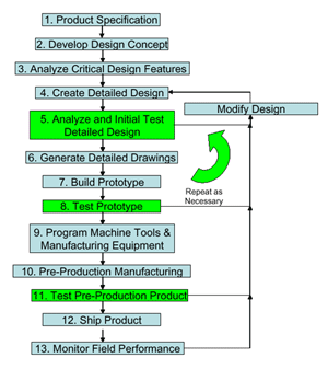
Figure 6 illustrates the design process with integrated system compatibility testing. This process served as the guideline during the development and testing of the many electronic ballast products. Lighting control designers can learn to apply the compatibility concept (See Figure 7) just as easy as ballast manufacturers have done. The process is basically the same, but the results will be different and just as valuable.
Figure 6. The design process with integrated system compatibility testing.
HOW COMPATIBILITY ENABLES LIGHTING CONTROL TO BE DEMAND RESPONSIVE
With basic lighting controllers having been developed several years ago, some with fairly mature designs, many controllers will continue to be used as individual systems separate from demand response (DR) systems. However, while the compatibility of a DR system is just as important as the compatibility of a lighting control system, the overall compatibility of a combined DR-lighting control system will be critical for facilities that begin to rely on them. Figure 7 illustrates this concept. Interestingly enough, many of the lessons to be learned regarding compatibility for lighting controllers will also be applicable to DR systems.
Figure 7. Compatibility concept applied to lighting controller, demand response system, and overall system.
CONCLUSION: SYSTEM COMPATIBILITY IS IMPORTANT FOR LIGHTING CONTROLS
As stated earlier, lighting controls are becoming a key part of a facility’s operating system. Prior to the use of lighting control, lights in a facility were just turned ‘on’ at the beginning of a day and turned ‘off’ at the end of a day. Now, facilities are having to become more intelligent and vary light levels according to occupant usage, space purpose, and ambient light levels. If facilities are to engage in energy savings using lighting controls, then the controls that they use must be hardened to the point where facility manages and occupants can expect them to function as desired in all types of electrical environments and building operating conditions. The electrical environment of the facility, including emissions and disturbances generated by the lighting devices themselves, must not impact the operation of lighting control systems.
Lighting controllers will need to function during thunderstorms, during electrical disturbances initiated by the public, and during electrical disturbances initiated by the utility. Lighting control designers may even want to consider integrating intelligence into the control that alerts the end user when an adverse condition exists such as the presence of a high level of electrical noise on one of the communication or port channels. Resolving a compatibility problem with a lighting controller before it shuts the building lighting system down would be very valuable. EPRI maintains expertise in solving compatibility problems with lighting controls. Expertise in this area can be used to further understand compatibility problems with lighting devices and control systems. End users simply cannot work in the dark, or under poor lighting conditions and in some conditions the failure of a lighting control system would present safety problems requiring the building to be evacuated. EPRI is positioned to further the maturity of lighting devices and controls through its research and testing in its Lighting Laboratory.
Philip F. Keebler manages the Lighting and Electromagnetic Compatibility (EMC) Group at EPRI where EMC site surveys are conducted, end-use devices are tested for EMC, EMC audits are conducted and EMI solutions are identified.
Kermit O. Phipps is a NARTE Certified engineer and conducts tests and evaluations of equipment performance in accordance with the EPRI System Compatibility Test Protocols for EPRI.
Frank Sharp is a Senior Project Engineer / Scientist at EPRI in Knoxville, Tenn.

