Introduction
This may seem disassociated from the electromagnetic compatibility (EMC) theme of this publication but issues dealing with power quality and the qualification testing has a direct link to EMC. Frequently the EMC engineers and technicians are tasked taking care of the power quality, so I believe that reviews of these standards are appropriate.
MIL-STD-1275 deals with characteristics of 28-volt DC input power to utilization equipment in military vehicles with revision “E” being the current edition issued in March 2013. Separate standards deal with ships and aircraft covered in future articles.
MIL-STD-461 is cited as an applicable part of MIL-STD-1275 along with Society of Automotive Engineers (SAE) J1113-42 Conducted Transient Emission test procedure (Note: ISO 7637-2 superseded J1113-42 in 2010). If the information in the reference documents conflicts with MIL-STD-1275, then MIL-STD-1275 takes precedence.
MIL-STD-1275 requires that the vehicle design authority deliver 28-V DC power to the utilization equipment power terminals that meets the requirements. This is a change from previous revisions where the power generation requirements were specified along with the utilization equipment requirements.
Although the standard states that electromagnetic interference (EMI) and electrostatic discharge (ESD) are not covered by the standard, most of the requirements are centered around EMI and ESD events.
Background
The standard goal is to provide compatibility between the vehicle power system and utilization equipment without undue restrictions of the power source by utilization equipment inability to tolerate vehicle power electrical events.
MIL-STD-1275A, issued September 1976, established several requirements dealing with steady-state conditions, spike, surges, and ripple of the power source supplementing the requirement for MIL-STD-461 compliance of the power system and utilization equipment. The requirement to define how the equipment shall operate during and after disturbances was to be determined by the procuring authority.
MIL-STD-1275B, issued November 1997, updated the requirements and included limits for fault conditions to be evaluated. Requirements for 14 Vdc components were established with the same limits as 28 V components.
MIL-STD-1275C, issued June 2006, updated the requirements and included a marked difference in the required temperature range for compliance. The new required evaluation temperature range was -45°C to +82°C versus the previous range of -32°C to +52°C. References to several SAE standards dealing EMC were added to supplement MIL-STD-461 requirements including ESD testing that was not present in MIL-STD-461. Conducted emission compliance to MIL-STD-461 was exempted for the vehicle power system.
MIL-STD-1275D, issued August 2006, made a few changes in requirements and definitions and notably reinstated the evaluation temperature range of -32°C to +52°C. Also, the exemption for conducted emission compliance of the power system was updated to just exempt CE102 compliance.
MIL-STD-1275E, issued March 2013, is the current revision and the requirements of this revision will be used for the discussion in this article. The evaluation temperature was established as ambient (+23°C ±5°C) but provided for extreme temperature evaluations at the discretion of the approving authority.
Data Item Descriptions (DIDs)
MIL-STD-1275 does not specify a DID for documenting the test and evaluation program, but the DIDs associated with MIL-STD-461 provide good outlines for test procedures and reports. It is generally accepted to follow these DIDs and I have included a section in the MIL-STD-461 documents to deal with the MIL-STD-1275 specific information. The document layout should be clear about what sections are MIL-STD-1275 related in case the approving authority is different than the MIL-STD-461 reviewers.
Requirements
The requirements specify the operating voltage limits and transient voltage characteristics at the utilization power input terminals. Voltage measurement tolerances are 1% unless otherwise stated.
Voltage compatibility requirements:
- Steady state operation requires operation between 20 and 33 VDC with testing at both limit extremes. Deviations from normal EUT operation is considered a failure. The steady state minimum and maximum voltage includes a short time period for the applied voltage to attain stability. The stabilization period duration allows for voltage to be between 18 and 100 Vdc for up to 50 msec attaining the normal voltage by 600 msec after initial power is applied (see Figure 8 in MIL-STD-1275E for the timing/voltage envelope). The test duration is not specified but allowing the EUT to reach thermal stability at each extreme is commonly accepted. Thermal stability is defined by temperature variation of less than 1°C for three consecutive measurements at 15-minute intervals.
When testing, pay attention to the facility ambient temperature—changes in ambient conditions makes tracking stability difficult.
- Voltage ripple on the DC voltage is considered part of the extreme amplitudes. Ripple testing uses MIL-STD-461 CS101 method to verify the EUT tolerance for the voltage variations classified as ripple. MIL-STD-1275 extends the test frequency range to 250 kHz (MIL-STD-461 upper frequency is 150 kHz) and keeps the limit at the same amplitude as the CS101 limit at 150 kHz. Testing is to be accomplished at 23 and 30 VDC power settings. EUT deviations from normal operation are considered failures.
If your qualification plans assumed that the MIL-STD-461 CS101 test would satisfy MIL-STD-1275 if you expanded the frequency range, you may need to do more than just up the frequency. Since MIL-STD-461 is tested at the nominal 28 VDC power input, you will need to retest at the 23 and 30 VDC input voltage settings.
Does testing at 30 VDC imply using the >28 V curve of MIL-STD-461? Not really since in MIL-STD-461 the curve is based on the nominal 28 VDC, to the curve should apply for both voltage settings.
Let’s not forget that MIL-STD-1275 calls for using 5 µH LISNs (Line Impedance Stabilization Network(s)), so the MIL-STD-461 CS101 testing with 50 µH LISNs may not be compatible. Consider that the test circuit characteristic impedance would be different depending on the LISN selected or consider using the 5 µH LISN for MIL-STD-461 testing—resolve in your test plan/procedure.
- Starting operation may be applicable to selected EUTs requiring that normal or limited functionality be maintained during the vehicle cranking operation. Figure 6 of MIL-STD-1275E provides the envelope of voltage extremes with timing during the starting operation. If applicable, then qualification testing should be included with the approving authority defining the operational requirements.
Transient disturbance requirements:
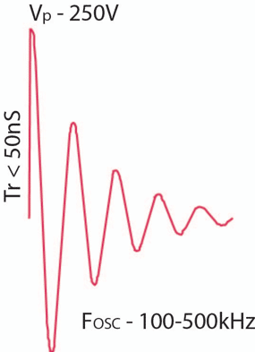
- Injected voltage spike testing is accomplished at the nominal 28 VDC power setting and 5 µH LISNs are required to isolate the power source. The spike waveform is defined (refer to Figure 1) as a damped cosine with an initial transition time of less than 50 nsec and oscillation frequency between 100 and 500 kHz. The waveform simulates transients into an inductive load present on the vehicle buss shared by the EUT. Fifty spikes with a peak of 250 V of each polarity are applied at 1-sec intervals.
The standard specifies that the maximum energy is 2 Joules (J) without defining the impedance or current limitation associated with the transient generator. The standard reads as if the energy limitation applies during the testing but without knowledge of the circuit under test, verification of the energy limitation is not feasible. The spike generator test circuit from MIL-STD-1275 revision “D” may be a good fall back method.

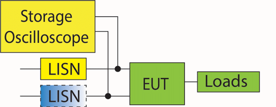
- Emitted spike testing is accomplished at the nominal 28 VDC power setting with power supplied via 5 µH LISN(s). Measurements of detected transients are made using a storage oscilloscope connected to the power terminals of the EUT minimizing the wire length to the measurement point (see Figure 2). Note that one of the LISNs may not be included in the test configuration. If the EUT chassis is the negative power terminal, a LISN is NOT in that line and the measurements are made referenced to the ground plane. During test the EUT switching functions capable of producing transients at least 32-times for each function to yield a reasonable probability of detecting a maximum spike amplitude/duration.
Figure 7 of MIL-STD-1275E provides a voltage envelope describing the maximum voltage for a spike duration. Detected spikes are compared to the limits defined by the envelope. The limit also includes an energy limit of 125 mJ, but without impedance or current data, calculation of the energy content is not feasible.

- Figure 2: Emitted Spike or Surge Test Configuration
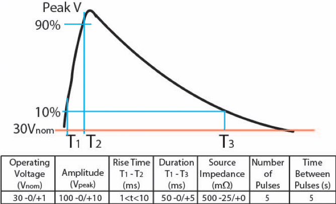
- Injected voltage surge testing is accomplished at a voltage input of 30 VDC (see Figure 3) with a tolerance of -0/+1 VDC as stated in the voltage surge test parameters (the waveform drawing shows V-nominal and that is specified as 28 V ± 1%). The stated energy limitation is 60 J with calibration of the waveform into a matched 500 mΩ resistance. Based on the waveform voltage and timing, the energy well exceeds 1 kJ. Not sure how the 60 J limit is maintained. During test, the impedance of the EUT transient protection would need to be high to limit the energy to 60 J.
The transient generator sketch is provided in MIL-STD-1275D, Figure 11 but most use the commercially available generator supporting the ISO 7637-2 surge testing (recall that ISO 7637-2 superseded SAE J1113-42 called out in the standard).

- Emitted surge testing is accomplished at the 28 VDC nominal input power setting in the same manner as emitted spike testing. The emitted surge voltage envelope is shown in MIL-STD-1275D, Figure 8 with the amplitude and timing of the transient making the difference between a surge and spike definition.
As with the spike testing, the functions of the EUT that could produce surges are exercised at least 32-times to provide a probability of capturing the maximum surge voltage.
Reverse polarity requirements
Reverse polarity testing connects the input power with the positive and negative power leads reversed. The power input is set to 33 VDC for this test and the test allows for at least five minutes of the reverse polarity being applied.
During test the current is monitored to verify that the reverse current does not exceed the normal operating current. After the test, configure the power input correctly and verify that the EUT operates as specified.
EMC requirements
MIL-STD-1275 does not cover EMC testing but does require that the EUT complies with the applicable EMC requirements – reference is made to MIL-STD-461.
ESD requirements
MIL-STD-1275 does not cover ESD testing but does require that the EUT complies with the applicable ESD requirements. The current revision “G” of MIL-STD-461 includes ESD compliance requirements.
Summary
MIL-STD-1275 should be viewed as supplemental to MIL-ST-461, not in conflict and not as a substitute. The requirements deal with power related issues and place specific test levels for vehicle systems. This supplemental approach helps avoid inclusion of EMC related events to devices that are not associated with the unique characteristics of vehicle issues.
Energy limits for the transient spikes and surges seems to be inadequately defined, so the test procedure should address this topic that includes how the device design will limit energy and the expectations during test.
Hopefully you will find this information useful, and I welcome questions.


