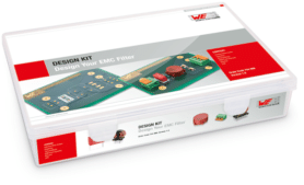
Some weeks ago I received one unit of the EMC-Filter kit from Würth Elektronik (Order Code: 744998), a very nice and useful kit for industry and academia (Fig. 1).

Fig. 1. The EMC-Filter kit from Würth Elektronik (Order Code: 744998)
If you are interested in filtering conducted emissions, this is a great kit for evaluation of components and topologies in both differential mode (DM) and common mode (CM) emissions.
The kit is specially useful combined with some kind of simulation tool (i.e. LTSPICE) and some frequency response analyzer as Bode100 from Omicron.
General view
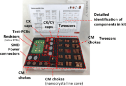
The box is included in a high quality plastic box with the traditional elegant style from the german manufacturer. Inside of the kit you will find (Fig. 2):
- Several PCBs offering an easy way to build up a line filter
- X capacitors for DM filtering (line-neutral)
- Y capacitors for CM filtering (line-earth and neutral-earth)
- Common mode chokes for CM filtering
- Resistors for discharging X capacitors as specified by safety rules
- Tweezers
- SMD terminals
- Plastic spacers
- Brochure and documentation
 Fig. 2. What you will find inside the kit.
The kit offers the user and easy way to evaluate the best topology for a given application using the Würth components but I think another great possibility is to use the kit to learn about EMC conducted emissions filters.
Topology and components
The integrated PCBs with different topopologies and footprints for components offer a simple way to try any design in a few minutes.
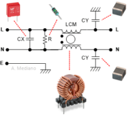
The basic topology implemented in the PCB boards is in Fig. 3:

Fig. 3. Basic topology in the kit.
As a general information for you, in my kit I found basically (this information is orientative and can change in future kits because I know designers in Würth Elektronik are always looking for better and new kits including new components for evaluation:
- 10 PC boards ready for soldering components using several footprints and combinations.
- Several X2 capacitors with 10nF, 15nF, and 150nF values and rated 275VAC. They will offer a low impedance path to high frequency signals trying to circulate in the LINE-NEUTRAL path.
- 10 resistors with 10Mohm values for discharging the X caps as mandatory from safety regulations. The resistors are connected in parallel with the capacitors.
- A good number of X1/Y2 capacitors with 680pF, 1nF, and 2.2nF values and rated 250VAC They will offer a low impedance path to high frequency signals trying to circulate in the DM (LINE-NEUTRAL) and CM (LINE-EARTH and NEUTRAL-EARTH) path modes.
- Several common mode chokes with 700uH, 1mH, 2.2mH, 3.3mH, 5mH, 6.8mH, 7mH, 9mH, 10mH, 20mH, and 27mH values. The chokes with 7mH and 9mH values are nanocrystalline technology. The CM chokes are used for filtering high frequency signals trying to circulate in the LINE-EARTH and NEUTRAL-EARTH paths (CM) offering a high impedance to those signals. In theory this component is transparent to the DM signals but, because of the leakage inductance, we will be able to offer some filtering effect with the CX capacitors for differential mode signals.
Using the kit and example
As soon as the kit was in my hands I tried one of the combinations. The process was easy: just choose your components and solder them in the PCB. No detailed analysis (to do later) but a fast working prototype that create enthusiasm for the topic.
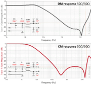
I decided to select one 150nF X capacitor, two 1nF Y capacitors, and one 5mH CM choke. The response of the filter in DM and CM modes was measured with my Bode 100 instrument as shown in Fig. 04.

Fig. 4. The DM and CM responses in my first prototype.
Note we can identifiy the attenuation at different frequencies in both modes, check for parasitic resonances because components and/or layout, and discover underdamping responses that can create special increase in emissions at some frequencies (e.g. 30-40kHz in DM mode).
The experience was really positive so, I recommend you to try the kit for your future EMC conduced emissions problems.


