ABSTRACT
Circuits are described that effectively protect RF, receiver, analog, and control line input circuits from three types of transient injection, described in DO-160, directly into the input pin of the connector.
The goal was to achieve a circuit which would not adversely affect the performance of the RF circuit over an input frequency range of 20MHz to above 1GHz with zero attenuation. The analog input was designed to have no more than 1dB of attenuation from dc to 20MHz. The RF circuit was tested both for RF performance and with the three types of transient specified by DO-160 injected into the input circuit.
Index terms – DO-160 pin injection test. RF and receiver input protection. 20MHz to above 1GHz operating frequency range, low VSWR, low attenuation. Analog input dc to 20MHz with low attenuation.
1. RF AND RECEIVER CIRCUIT INTRODUCTION
When a significant series impedance can be inserted in the RF circuit followed by diodes to the supply rail and power return this can provide adequate protection. However the goal is that the circuit has only 0.27dB total loss, which includes attenuation and mismatch loss, and so precludes the addition of any series impedance.
Low capacitance Transient Voltage Suppressor (TVS) which includes a low capacitance series diode in series with the TVS are available but even the low capacitance results in an unacceptable VSWR loss above about 100MHz.
These and other devices for protection are described in reference 1.
The DO-160 pin injection is conducted between the pin and chassis with the Equipment Under Test (EUT) powered up.
If the RF ground is isolated from chassis with a sufficiently high impedance over the frequency range typical of the pin injection waveforms, then both the input circuit and the RF ground will rise in potential above the chassis to the test level. If this technique is used it is thus important that any circuits, such as the input of isolated switching power supplies, are able to withstand the voltage, of up to 600V. In most RF circuits, the RF ground is chassis ground, and that is the assumption used in the design of the protection circuit, so isolation is not feasible.
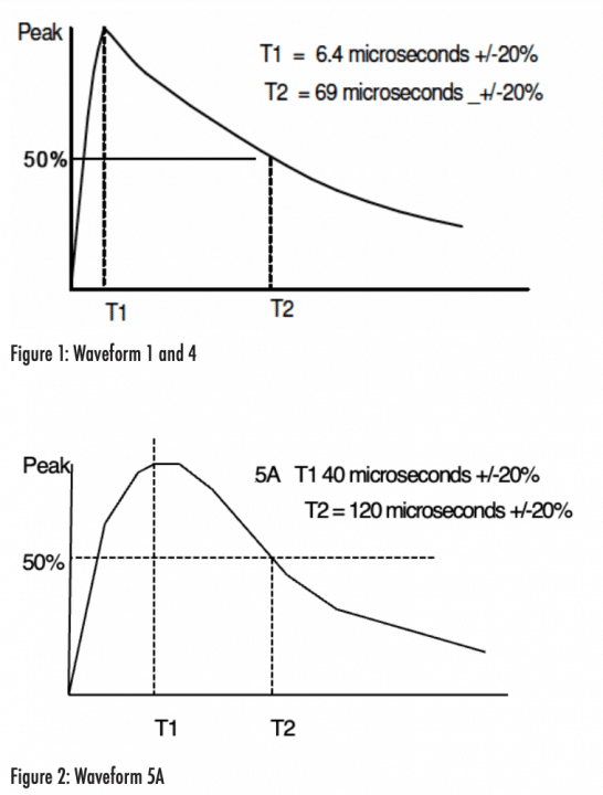
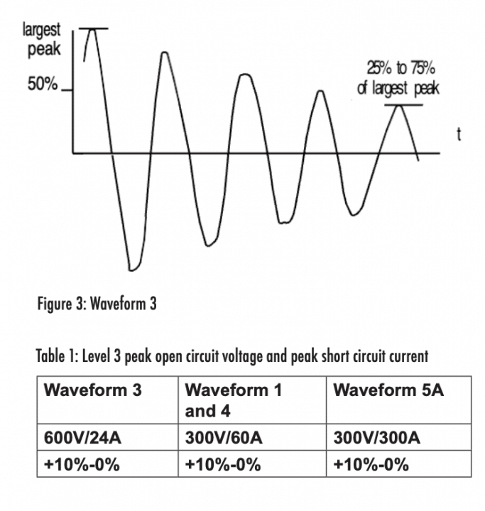
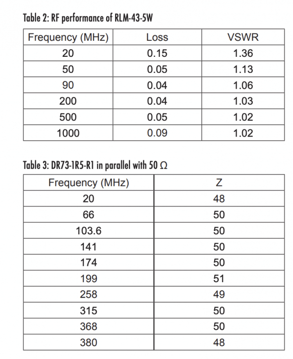
The DO 160 pin injection waveforms are transient current waveforms 1/ 3, 4 and 5A or 5B with waveform 5A more common than type 5B. These waveforms are shown in figures 1, 2 and 3. The test levels are specified from 1-5 with 3 the most common maximum level and this was used in the development of the protection circuit. The peak open circuit voltage and peak short circuit current at level 3 are shown in table 1.
DO-160 also specifies a cable bundle test which is used to evaluate the functional upset tolerance of equipment when transients are applied to interconnecting cables. As the majority of RF circuit interface cables are shielded, and often analog interfaces, and use shielded connectors the level of shielding effectiveness thereby achieved means that it is highly unlikely that the input circuit will be damaged by the transients, although an upset may occur, depending on the RF signal level. An input impedance of 50 Ω is used in the development of the protection circuit as this is the most common input impedance for RF circuits.
2. RF PROTECTION CIRCUIT
Adding an inductor in parallel with the 50 Ohm input impedance can represent a low impedance to waveform 1, 3 and 5A but a high impedance from 20MHz and above to the RF signal. Above some frequency the inductor will modify the VSWR of the input. An arbitrary maximum VSWR of 1.1 was used in selecting the inductors.
The inductors chosen were designed for power as they are most likely to withstand the high transient current. They are rated for dc current and no information was available on the transient current carrying capability. Instead the inductors which were found ideal, based on their RF performance, were tested with 50 positive and 50 negative transients and the dc resistance and inductance were measured before and after exposure. All of the inductors tested were unchanged after this testing.
The inductors tested had values of 220nH, 470nH, 1µ H, 1.5 µ H, 2 µ H, 4.7 µ H,10 µ H and 23 µ H.
The 1.5 µ H part number 744314150 measured 48Ω or higher from 20MHz to 337MHz.
The 1.5μ H part number DR73-1R5-R1 Measured 48Ω or higher from 20MHz to 380MHz.
The 744314150 inductor is manufactured b Wurth and the DR73-1R5-R by Eaton Electronics Division.
The DR73-1R5-R1 saturates at a current of 6.52A and then it is the dc resistance of 0.013 Ohm which is across the input circuit.
The dimensions of this inductor are 7.5mm x 7.5mm with a height of 3mm.
The DR125-1R5-R, also manufactured by Wurth, is also 1.5uH in value but has an even lower resistance of 0.0029 Ohm. This inductor was not tested.
The Wurth and Eaton inductors were both tested and passed the transient injection test and it was decided to proceed testing with the 1.5 μ H DR73-1R5-R1 inductor. The impedance of the DR73-1R5 in parallel with 50Ω is shown in table3 and the maximum VSWR is 1.0417.
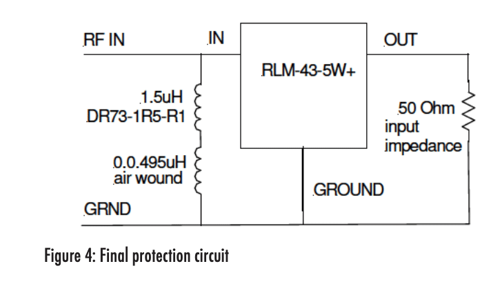
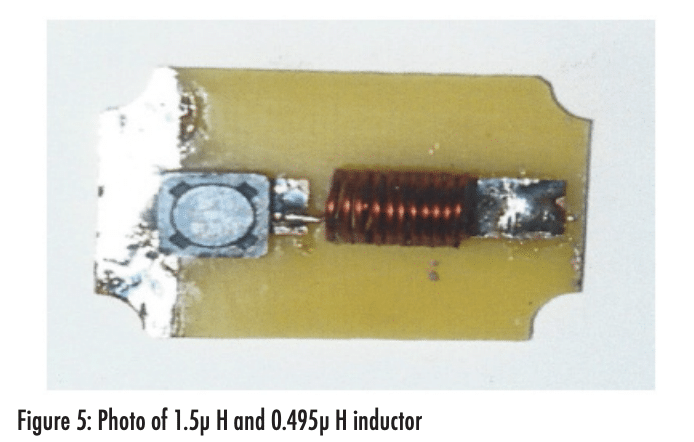
To increase the frequency range further a 11 turn air core coil was wound with a diameter of 6.5mm and a length 9mm and with an inductance of 0.495 µ H. This was added in series with the 1.5 µ H DR73-1R5-R1 inductor, as shown in figure 5. The impedance of both inductors when in parallel with a 50Ω resistor was 48.5Ω at 500MHz and 49.2Ω at 1GHz thus the useful frequency range of the combination 0.495uH and 1.5uH was 20MHz to 1GHz.
The 220nH and 470nH fixed power inductors did not perform any where near as well as the air wound coil.
The voltage developed across the 50Ω load and 1.5 µ H inductor with the 6.9 µ S/69 µ S 300V/60A waveform 1 / 4 was 61V. The voltage developed across the 50Ω load and 1.5 µ H inductor with the 40 µ S/120 µ S, 300V/300A waveform #5A applied was 35V with a 9 µ S pulse width at 50% amplitude.
These levels are still too high. Also the damped sine wave, waveform 3, is usually tested at 1MHz and 10MHz and the impedance of the 1.5 µ H inductor is too high at 10MHz to reduce the test level sufficiently. However due to the short duration of the resultant damped sine wave transients the electrical energy is much lower than in the applied pulse test transients as the half cycles in the 1MHz and 10MHz damped sine wave have a short duration.
The use of a limiter to further reduce the transient across the inductor was examined. The 1N5711 and BAT81S small signal schottky diodes in parallel with the 1.5 µ H inductor were tested and both failed with the 40 µ S/120 µ S pulse applied.
Mini-Circuits Manufacture Small Limiters
An application engineer at Mini-Circuits suggested the RLM-43-5W+ which can handle 37dBm (5W) but could not predict the performance with the transients generated across the 1.5 µ H and 0.495uH inductors. The frequency range of the RLM-43-5W+ is 20MHz to 4000MHz.
The loss and VSWR are shown in table 2.
The Mini-Circuits engineer’s recommendation was to test it and that is what was done.
The final protection circuit is shown in figure 4 A photo of the 1.5μ H in series with the 0.495μ H inductor is shown in figure 5.
To prove that the 1.5μ inductor is necessary the RLM43-5W was tested without the 1.5μH inductor but as expected failed open circuit.
3. TEST RESULTS WITH FINAL CIRCUIT
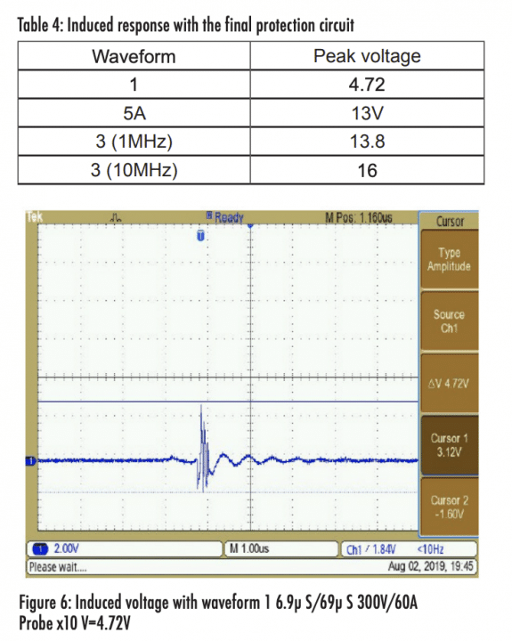
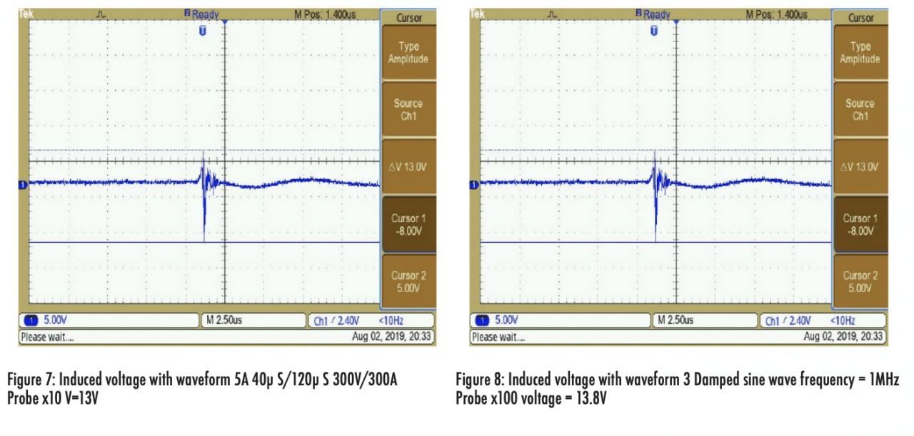
The circuit was tested with 50 positive and 50 negative transients for each of the four tests and the resultant induced transient remained the same throughout.
Table 4 shows the amplitude of the induced transients for each test.
4. ANALOG AND CONTROL LINE. 5. ANALOG CIRCUIT INPUT PROTECTION
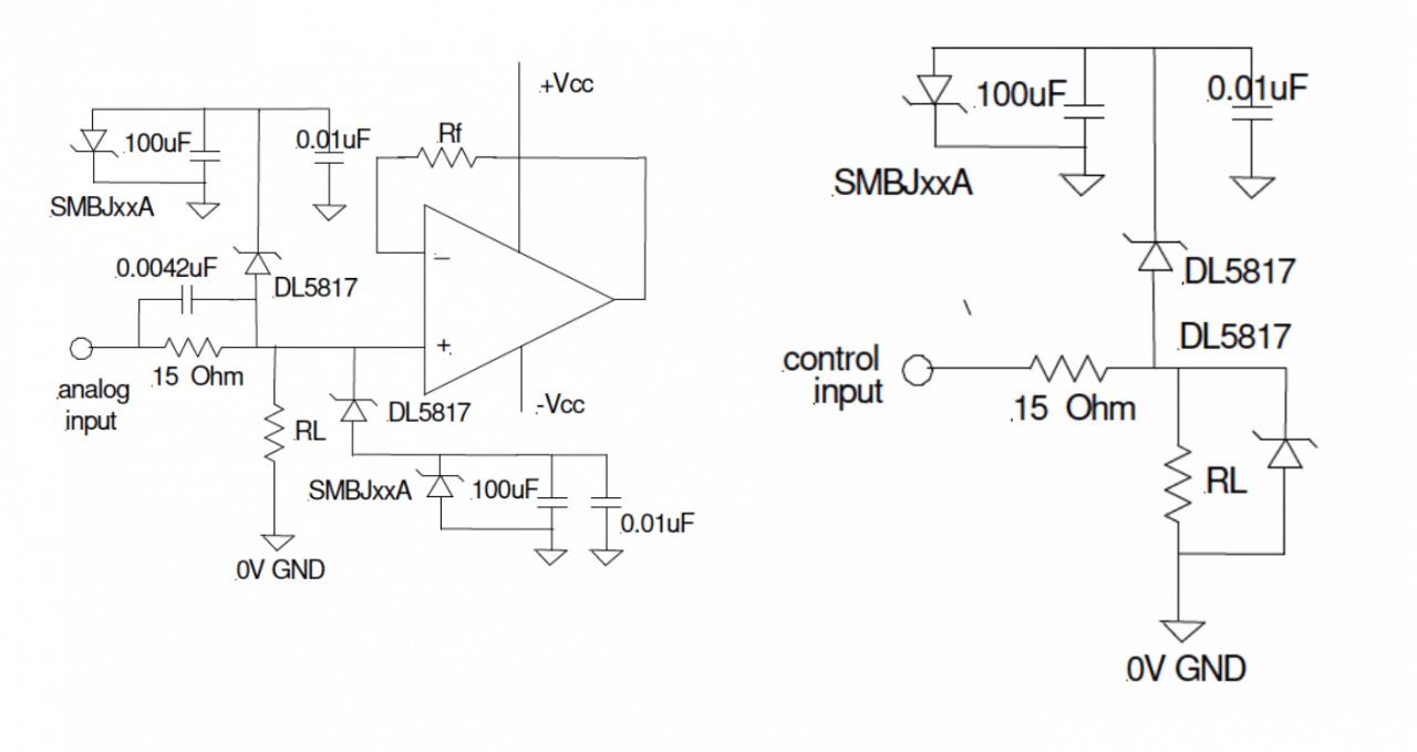
The circuits are shown in figure 5. and 6
6. CONTROL LINE CIRCUIT PROTECTION
The DL5817 Schottky diodes are used to clamp the input transients to just above the positive supply voltage and the negative transient to just below 0V or below -Vcc. The DL5817 Schottky diode could be connected to +Vcc and -Vcc and the SMBJxxA Transorb removed. However this means that the power supplies must sink the transient current. With a 600V 24A transient applied the generator source impedance and the 15 Ohm resistor will limit the current through the diode to 15A, With 300V 60A applied, the current through the diodes is maximum 15A and with 300V 300A supplied the current through the diodes is maximum 19A. Instead of sinking the current the supplies output voltages are likely to increase above the rated power supply voltage. The circuits in figures 5 and 6 shows the protection circuit disconnected from the supply voltages and instead connected to the Transorb.
On application of the transient the 100uF capacitor begins to charge up and at some voltage the Transorb clamps the voltage. If the DL5817 is connected from the input to ground, as shown in the control circuit, then the peak current is 19A with a duration (from 0A to 0A) of approximately 300uS. The DL5817 is rated at peak 25A for 8.3mS half sine and so is well derated.
For a 12V supply the SMBJ10A would be a good choice with a breakdown voltage of 11.7V at 1ma. Adding the DL5817 approximate forward voltage drop of 0.3V at 1mA, the input voltage will be 12V. With the longest duration transient, the 40/120uS, the maximum current through the SMBJ10A will be 8.5A and the approximate voltage drop is 13V. Adding the voltage drop of the DL5817 at 8.5A of 0.8V the input voltage is limited to 13.8V. The maximum rated current of the SMBJ10A for a 10/1000uS pulse is 60A and so is well derated. The attenuation at low voltage is due to the divider resulting from the 15 Ohm series resistor and the load resistor. Assuming the load resistor is 1kOhm then the attenuation at low frequency is 0.13dB.
The typical SMBJ10A diode junction capacitance is 300pF at 0.1V. Due to the 0.0042uF capacitor in parallel with the 15 Ohm resistor the attenuation at 20MHz with a high impedance load or a 1kOhm load is then approximately 0.6dB.
About the Author
David A. Weston has worked on EMI problem solving and the EMC design of Space, aircraft, rail, military and commercial equipment, subsystems and systems over the last 41 years. He is author of the third edition of the 1200 page book Electromagnetic Compatibility: Methods, Analysis, Circuits and Measurements, Published August 2016 as well as numerous articles and papers.
References
1. Electromagnetic Compatibility: Methods, Analysis, Circuits and Measurements, third edition, D. A. Weston, CRC Press, Taylor and Francis Group, 2016


