Protection of a power system’s electrical equipment from a high-altitude (more than 30 km) nuclear explosion (HEMP) impact is a challenging issue, which until recently has not received proper attention. The fact is that HEMP does not affect people directly, while the electromagnetic pulse resulting from this explosion is a powerful devastating factor for the power grid’s electronic and power supply equipment. Since the electrical power industry is the foundation of any country’s infrastructure, such a feature of HEMP is very attractive for the military.
HEMP is known to consist of three components: E1, E2 and Е3. These are significantly different from each other in terms of their properties and specifications, due to a full set of complex physical effects occurring in the ionosphere upon nuclear explosion. For example, while the E1 component represents a short single pulse (2.5/25 ns) creating very high electrical field strength at the ground surface (50 kV/m), the E3 component is inversely a very slow oscillating process with a frequency of less than 0.1 Hz and low electrical field strength (up to 85 V/km) [3], which lasts several minutes. The E2 component is very similar to lightning in terms of its impact and thus protection of this equipment has been envisaged.
This article discusses protection of the electrical grid’s power equipment from HEMP’s E3 component.
E3’s Impact on Electrical Power Equipment
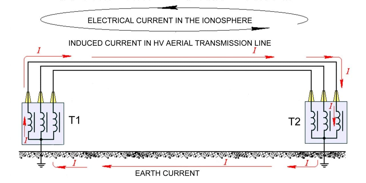
It may seem that the issue of protection from slow electromagnetic oscillations with such low electrical field strength as 85 V/km is exaggerated, nevertheless this is true at the first glance only. Indeed, these electromagnetic oscillations are induced in many kilometer-long overhead power transmission lines and closed through a very low impedance loop, e.g. a grounding system (Fig. 1). As a result, geomagnetically-induced quasi-DC currents (GIC) with an amplitude of dozens and hundreds of Amps may pass through neutral conductors of power transformers. This leads to quick saturation of the transformer’s core and consequently reduction of its impedance. Concurrently, operational current flowing through its windings will increase, resulting in the transformer’s excessive heating. Similar impact of geomagnetically-induced currents caused by solar storms in the Northern Hemisphere (Canada and USA) resulted in coils blowing of powerful power transformers that cost several million dollars. Apart from the high cost of such transformers, other problems would include long-term manufacturing of such equipment and complicated transportation of it to the point of use. That is why malfunction of such transformers represents an emergency situation for power systems requiring costly efforts to prevent them in the future.
The SolidGroundTM device promoted by ABB is meant for blocking GIC in neutral conductors of power transformers (Figure 2).
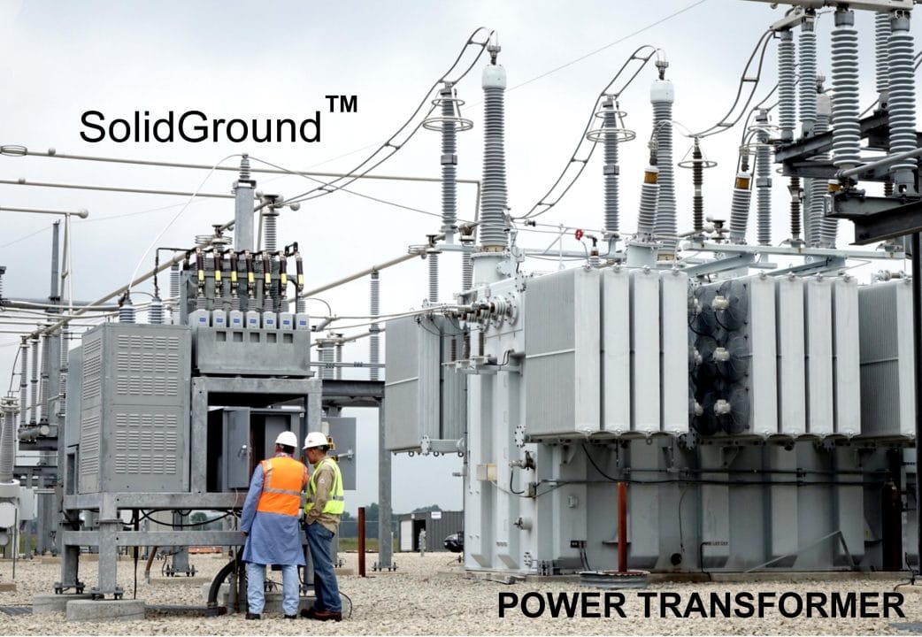
Figure 2 shows that this device is an expensive (more than $300,000 [5]) high-voltage unit, which requires ample space to be mounted at a substation site. Initially, this device was developed to block GIC during severe solar storms, which may last for many hours. Later on, it was promoted as a main remedy to block the E3 component of HEMP [4, 6], which lasts several minutes only. However, this difference has never been mentioned in technical literature. Alternatively, the developers (in order to promote this expensive piece of equipment) suggest that there is almost no difference between a solar storm’s GIC and that induced by HEMP, e.g. [7]:
- “… mitigation options against GIC in power systems are also suitable for mitigation against nuclear EMP E3 events”.
- “The 2008 EMP commission report states “steps taken to mitigate the E3 threat also would simultaneously mitigate this threat from the natural environment”.
- “An EMP model of the SolidGround™ neutral blocking device (NBD) which is capable of protection against higher EMP E3 levels … has been designed, tested and is available”.
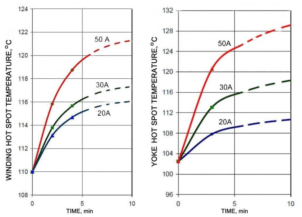
Field strength of the E3 component: 85 V/km is a value close to maximum, which depends on multiple external factors (geographical location of transformers and overhead power transmission lines, grounding system resistance, soil properties, design of the transformers’ core, etc.) and thus GIC in the transformer’s neutral conductor will not necessarily be equal to hundreds of Amperes. With the current of several dozen Amperes passing through, several minutes is not sufficient for a big power transformer containing tons of steel, copper, and oil to heat up to dangerous temperatures.
Does it mean that the problem does not exist and we can neglect GIC occurring as affected by the E3 component in most cases? This conclusion was made by the authors of the renowned Electrical Power Research Institute (EPRI) [8]. Nevertheless, it should be admitted that the conclusion of EPRI regarding HEMP impact on the power grid’s electrical equipment faced severe criticism from corresponding experts.
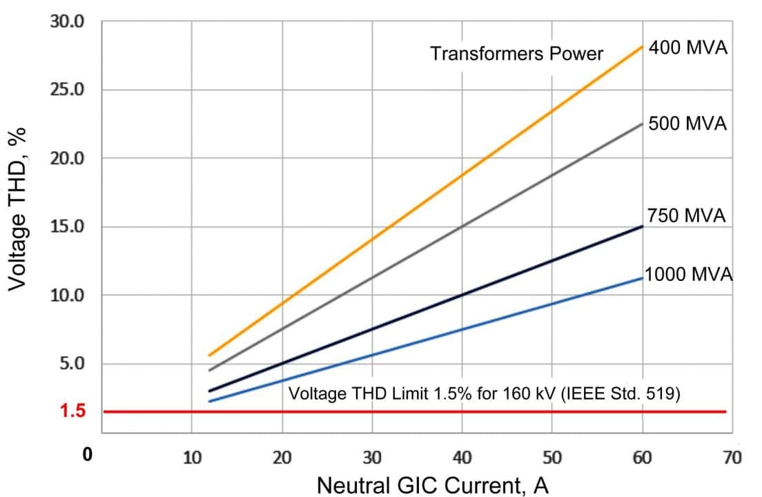
Yet, feasibility of significant investments into HEMP protection of power transformers still needs to be addressed. It should be kept in mind that; (i) the probability of high-amplitude GIC occurrence still exists (under specific combination of external parameters and conditions); and (ii) a power transformer with a saturated core acts as a powerful source of harmonics generated into the power system (Figure 4). These harmonics can negatively affect many types of electrical equipment in the power system, e.g. capacitor banks of longitudinal and transverse capacitive compensation, relay protection devices, etc.
Another issue is a sharp loss of reactive power in the grid upon GIC impact onto power transformers and further sharp reduction of voltage. As a result, the power system’s stability is compromised potentially leading to its collapse.
It is very difficult to predict or assess the behavior of the specific power grid upon E3 impact, however, it is worth taking preventive measures when considering the possible damage. What are these measures? Are there any other solutions apart from extremely expensive and bulky units offered by ABB?
Suggested Solution for the Problem
The solution of the above-mentioned problem (protection of the power grid’s electrical equipment from the E3 component of HEMP) is based on the difference between GIC occurring during solar storms and GIC occurring during high-altitude nuclear explosion. This solution was offered by author back in 2011 [11, 12]. The idea behind it involves a short-term automatic disconnection of the power transformer (achieved by HEMP-protected relay upon sensing GIC in the neutral conductor) with further automatic return to operation after a several-minute pause (i.e. when the E3 impact is over). This solution was realized with the special electronic relay, developed by author. This relay suitable for large-scale use and to be conveniently implemented in power systems. The protection relay includes the GIC sensor designed as a portable current transformer to be put on the cable, grounding the transformer neutral and a special relay, which responds to a signal from the GIC sensor. The equipment also includes a tester for periodical testing of protection relay serviceability directly at the installation point by means of GIC simulation.
Unfortunately, the selection of GIC sensors available in the market is very limited. There are few companies that manufacture these devices, such as: Dynamic Ratings (GIC-4), Weidmann Electrical Technology Inc. (InsuLogix), Advanced Power Technology (Eclipse HECT), Ohio Semitronics, Inc. (GIC-051D). Upon analyzing technical specifications and conducting cost comparison, was selected GIC-051D by Ohio Semitronics, Inc. as the most suitable and simultaneously the cheapest device from all available in the market (~$700), Fig. 5.
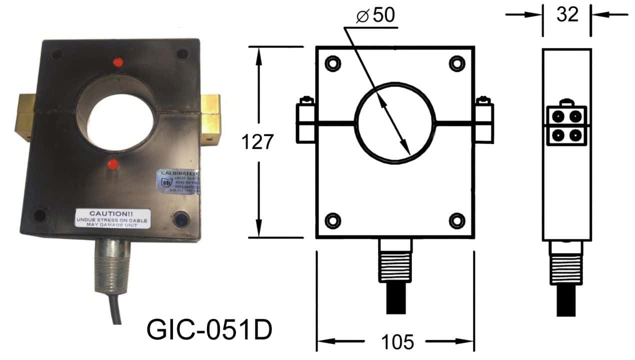
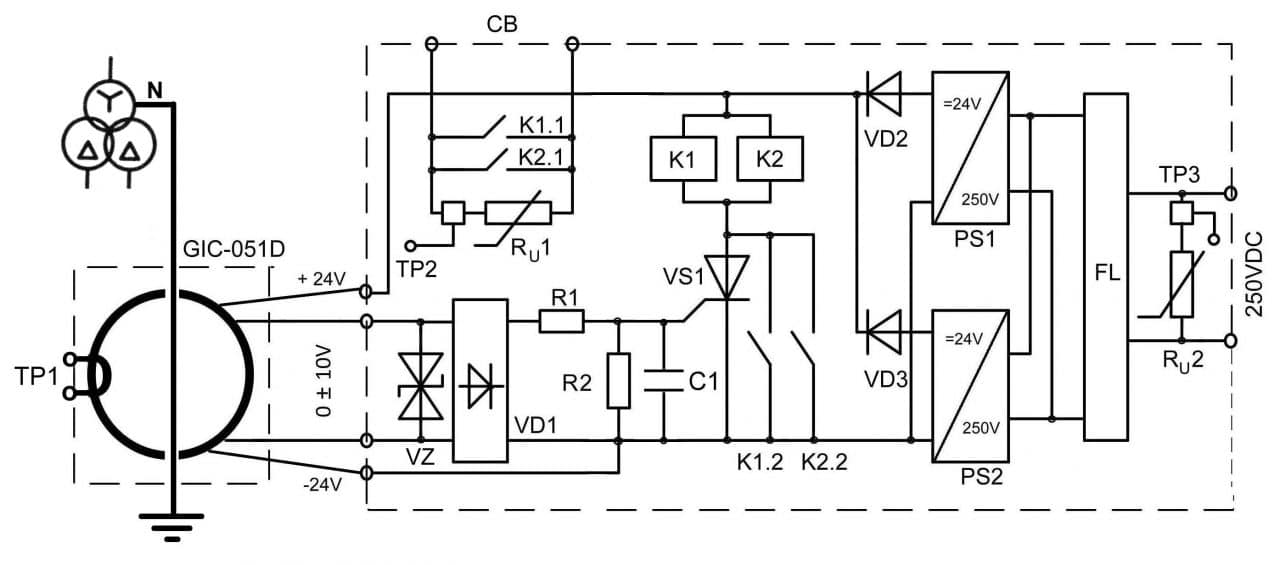
This sensor is placed on the cable, grounding the transformer neutral, and provides 0 V to 10 V output voltage only in case 0 to 50 A, 0 -1.5 Hz quasi-DC current of any direction occurs in that cable (i.e. it does not react to 50 Hz AC current). The sensor can sustain short-circuit current up to 8 kA in the cable without any damage. The sensor’s tolerance is 0.5% of the full current rating (0.25 A for this design). The sensor is connected to the input of the improved reliability protection relay developed by author (Fig. 6)
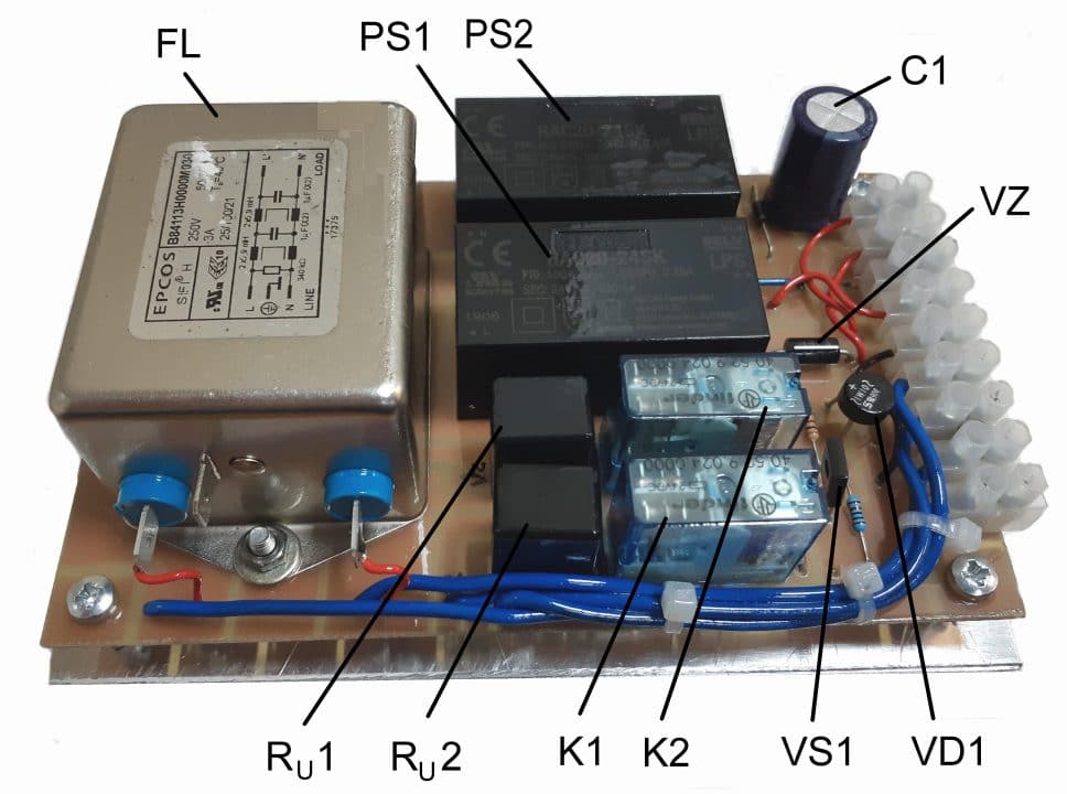
Prototype of electronic relay (Figure 7) was constructed and tested by the author.
Under the normal mode of the power grid’s operation it is only the alternating current that can pass through the cable grounding the neutral of the power transformer’s coil “wye” connected. A high-altitude nuclear explosion will generate a direct current component (E3 component) in the cable, which produce voltage at sensor output proportionate to that current to the GIC-051D sensor’s input. If the current value exceeds 20A, the output voltage from the sensor will be high enough to open the thyristor VS1. Its opening threshold has been set constant and unadjustable by means of any tuning element potentially affecting the relay’s reliability. The threshold is determined by the R2 resistor value and is set up during manufacturing of the relay.
Opening of the thyristor VS1 triggers two electromagnetic relays (K1 and K2) with parallel contacts. The first pair of contacts controls the trip coil of the high-voltage circuit breaker through the substation’s auxiliary relay (to disconnect the transformer), while the second pair shunts the thyristor VS1, protecting it from overheating by the passing current and preventing multiple actuation and releasing of the relay during current surges in the above-mentioned cable. Several minutes later (i.e. when the impact of the E3 component is over), the automatic reclosing system on the substation will return the transformer back to the operating mode. The same system performs short-term interruption of the power supply of GIC protective relay though an auxiliary timer. This short-term power supply interruption is enough for the GIC protective relay to return to the initial condition, i.e. into a stand-by mode.
The printed circuit board is coated with two layers of high-quality water-resistance varnish on both sides and is placed into a sealed aluminum container, which ensures the circuit’s protection from the E1 component of HEMP. The sensor is also placed into a similar shielding container. The circuit is then connected to external circuits by means of a shielded cable.
Tester for Periodical Testing of Relay Serviceability
As mentioned above, the power transformer is the major part of the power supply system. Thus, reliability of its protection system is of utmost importance. In order to be sure that the GIC protection relay is serviceable, it needs to be periodically tested. A special portable tester (Figures 8 and 9) has been developed and constructed by the author for periodically serviceability testing of the abovementioned protection relay placed on the grounding cable of the transformer’s neutral.
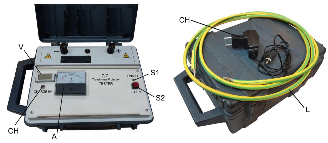
The tester is powered by one 6 V, 12 A/h battery. The battery’s current (about 25 A) in the tester prototype is limited by two 100 W, 0.1 Ohm resistors R1 and R2 connected in series. This power allowance has been provided in order to prevent heating of the resistors and changing of their resistance (i.e. output current of the tester during its operation). The tests have shown that one 100 W, 0.2 Ohm resistor mounted on an aluminum panel is sufficient. The tester’s output current is supplied to a flexible cable L, made of insulated copper wire placed for testing purposes into the GIC-051D sensor’s window (Fig. 9).
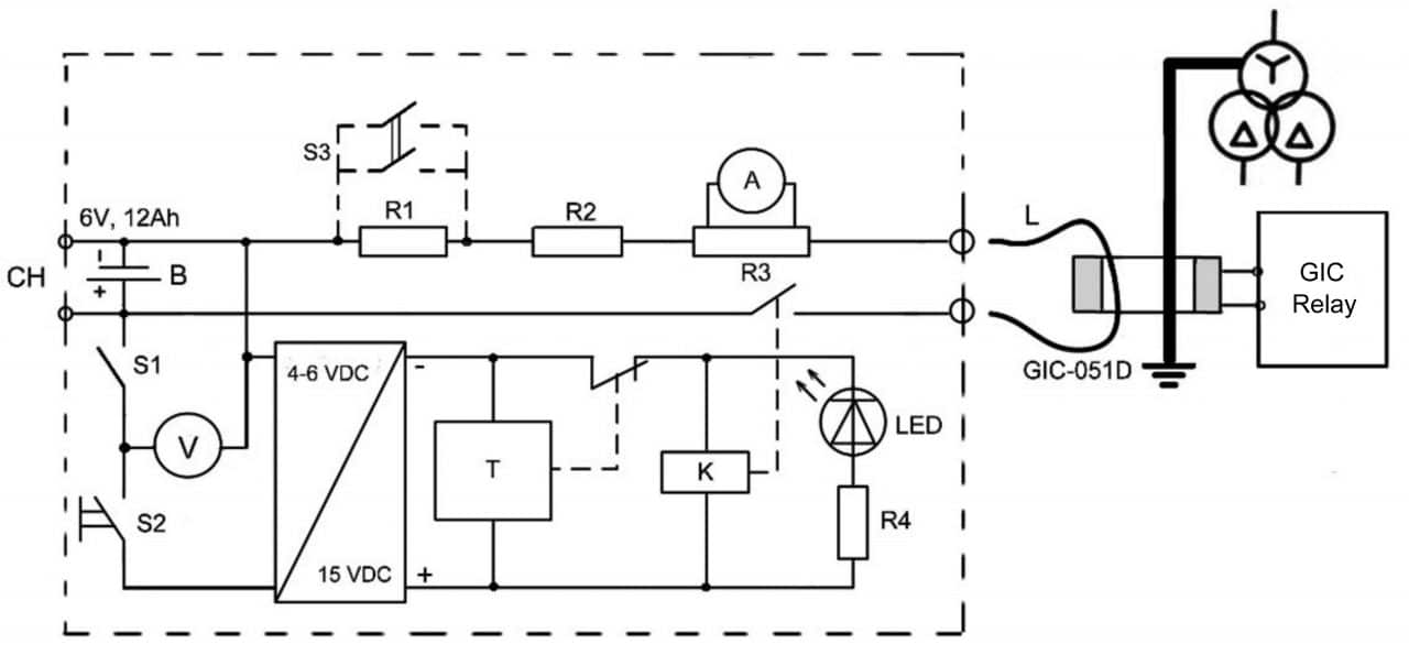
The tester can be upgraded by using two stages of output current. The lower stage serves to check failure of GIC protective relay actuation at current values slightly lower than its trip threshold, while the upper stage serves to check actuation of GIC protective relay at current values slightly higher than its trip threshold. This upgrade can be implemented by using an additional two-pole toggle-switch (S3) with switching contacts designed for 20 A (see the dotted line in Figure 9).
Conclusion
The set of devices described above solves a problem of protecting power transformer (major element of an electrical power supply system) against HEMP and from consequences of its impact onto the power grid altogether. These device designs are very simple, inexpensive and are suitable for mass production. With this set of equipment, the issue of HEMP impact onto a power supply transformer can be deemed completely resolved.
References
[1] Gurevich V. Protection of Substation Critical Equipment Against Intentional Electromagnetic Threats. – Wiley, 2017. – 228 p.
[2] Gurevich V. Protecting Electrical Equipment: Good Practices for Preventing High Altitude Electromagnetic Pulse Impacts. – De Gruyter, Berlin, 2019. – 386 p.
[3] Recommended E3 HEMP Heave Electric Field Waveform for the Critical Infrastructures. – Report of the Commission to Assess the Threat to the United States from Electromagnetic Pulse (EMP) Attack, 2017.
[4] SolidGround™ neutral blocker is the most effective and economical solution to protect the electric power grid from stray DC, Solar Storms (GMD) and Nuclear EMP E3 – http://www.emprimus.com/solidground
[5] Power World Grid Modeling with GIC and Neutral Blocking. – Presentation to 2013 Power World Client Conference January 22, 2013.
[6] SolidGroundTM Grid Stability System Geomagnetic Storm Induced Currents (GIC) and Electromagnetic Pulse (EMP) E3 Protection. – ABB Inc. High Voltage Products, 2012.
[7] Faxvog F.R., Fuchs G., Jensen W., end etc. HV Power Transformer Neutral Blocking Device (NBD) Operating Experience in Wisconsin. – 53-rd Annual Minnesota Power System Conference (MINPSYCON), University of the Minnesota, November 7 – 9, 2017.
[8] Magnetohydrodynamic Electromagnetic Pulse Assessment of the Continental U. S. Electric Grid. – Report EPRI No. 3002009001, February, 2017.
[9] Analysis of Geomagnetic Disturbance (GMD) Related Harmonics. – Report EPRI No. 3002002985, March, 2014.
[10] IEEE Std. 519 – 2014. IEEE Recommended Practice and Requirements for Harmonic Control in Electric Power Systems, 2014.
[11] Gurevich V. The Power Transformers are Also Affected by the Sun – Electrical Market, 2011, No. 5, pp. 48 – 51 (rus).
[12] Gurevich V. Protection of Power Transformers Against Geomagnetically Induced Currents. – Serbian Journal of Electrical Engineering, 2011, Vol. 8, No. 2, pp. 333 – 339.
[13] Horton R. Perspectives on Protecting the Electric Grid from an Electromagnetic Pulse or Geomagnetic Disturbance. – Hearing of the U.S. Senate Homeland Security and Governmental Affairs Committee, February 27, 2019.


