INTRODUCTION
There is a transmission line critical length rule that is often used in high-speed PCB design by novice engineers. This rule should not be used and is not appropriate for high-speed PCBs.
The bandwidth limit of a digital signal or a high-speed digital channel is often used in certain calculations to get estimates of channel behavior. For example, the knee frequency is often used to understand how small impedance discontinuities might affect signal propagation, or it may be used to understand the maximum expected dielectric or conductor losses. It is important to understand the bandwidth your channel needs in relation to signal bandwidth.
Unfortunately, knee frequency is a misleading metric that is often misinterpreted. It is most often incorrectly cited as the limit of a digital signal’s bandwidth. This is not exactly correct, and it only becomes correct in an ideal situation that is not observed in reality.
WHAT IS THE KNEE FREQUENCY?
In high-speed digital design, the knee frequency is sometimes used to calculate signal integrity metrics. The -3 dB for a high-speed channel is often cited as the following formula:

where the t(rise) term in the denominator is a 10%-90% rise time for the signal.
Many guidelines will cite the knee frequency with a coefficient of 0.5 instead of 0.35. Regardless of the coefficient or name, the knee frequency/-3 dB frequency will then be cited as the upper limit of a digital signal’s bandwidth as a function of the input signal’s 10%-90% rise time. This is incorrect. In fact, the knee frequency tells you a channel’s response to a perfect square wave. The input square wave has a rise time of 0; the rise time cited above is the edge rate of the signal as one would measure at the receiver. Furthermore, it ignores loss in the channel and pin/package inductance.
Many guidelines will cite the knee frequency with a coefficient of 0.5 instead of 0.35. Regardless of the coefficient or name, the knee frequency/-3 dB frequency will then be cited as the upper limit of a digital signal’s bandwidth as a function of the input signal’s 10%-90% rise time. This is incorrect. In fact, the knee frequency tells you a channel’s response to a perfect square wave. The input square wave has a rise time of 0; the rise time cited above is the edge rate of the signal as one would measure at the receiver. Furthermore, it ignores loss in the channel and pin/package inductance.
Instead, we first have to notice three points about digital signals and high-speed channels:
1. Most high-speed channels are modeled as being terminated at some target impedance
2. There is a load capacitance, and package parasitics, that affect the rise time seen at the receiver
3. The losses in the channel limit the bandwidth, regardless of how the channel is terminated
The result of these three points is that the edge rate seen at the receiver is not the same as the edge rate of the signal injected into the transmission line by the driver. So which one defines the bandwidth of a digital signal? The answer is: neither of these!
FACT #1: DIGITAL SIGNALS HAVE INFINITE BANDWIDTH
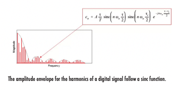
Probably the most often quoted point about digital signals is that they have finite bandwidth, and the bandwidth limit is the knee frequency. This is incorrect. All digital signals have infinite bandwidth, and this can be derived by calculating the Fourier series of a trapezoidal signal, Gaussian/error function edge rate signal, or Lorentzian edge rate signal. No matter how you approximate the signal’s edge rate, you will find that the bandwidth is infinite.
While I won’t belabor the derivation of a digital signal’s bandwidth in this article, I’ll instead show the important result with which digital designers and EMC experts should be familiar. If you approximate a digital signal as a trapezoidal wave, you will find that the amplitude envelope on the wave’s harmonics is a sinc function. This is how we get the well-known graph such as that shown below.

If a real digital signal with an imperfect edge has infinite bandwidth, does the channel also need to have infinite bandwidth? The answer is a definite “no” as I’ll outline below.
FACT #2: HIGH-SPEED CHANNELS DO NOT NEED INFINITE BANDWIDTH
Although digital signals do not have a bandwidth limit, real interconnects do have bandwidth limits. The bandwidth of a channel is limited by the following factors:
• Frequency-dependent Insertion loss in the channel (dielectric, conductor)
• Return loss from vias, land pads, connectors, cable interfaces, etc.
• The termination at the receiver, which may be an LC circuit model
• Noise in the channel
As long as you design a channel to provide the minimum amount of bandwidth, then the channel should work properly for a given noise limit. The trick is determining that exact limit, which requires knowing the requirements for your receiver to determine a logic state from a received signal.
Finally, in systems where channel bandwidth calculations are very important, the required channel bandwidth generally may have no explicit relation to rise time. Today, this comprises the majority of computing and networking interfaces. For example, in bitstreams that use pulse-amplitude modulation (PAM), the required channel bandwidth is based on the receiver’s sample rate and is calculated using the Nyquist theorem. For a modulated signal transmitting a data rate D with N signal levels per signal would require a minimum channel bandwidth of:

While it is true that data rate generally correlates with signal rise time, there is no explicit relationship or requirement; different transmitters could source signals with different edge rates and the channel will still work. For example, if we look at a 112G PAM-4 bitstream with a 25% UI rise time, we would find that the minimum channel bandwidth is 40 GHz. The receiver only requires a channel bandwidth of 28 GHz, so we find that using the signal rise time to determine a design constraint sets an unrealistic design target for our high-speed channel.
CONCLUSION
In conclusion, the knee frequency formula has very limited applicability and is no longer a valid metric for describing bandwidth requirements in real high-speed channels. At best, it is an approximation for single-ended channels with a known rise time requirement at the receiver.
This is because losses and the termination create a very complex bandwidth vs. rise time relation. When we look at differential channels, which comprise most high-speed interconnects, the model leading from a component landing pad to the on-die termination circuit can be an LC circuit, depending on the package design.
If you wanted to calculate the response of a real transmission line to an arbitrary input signal, you would need to determine a transfer function for the channel and use the channel’s impulse response function. If you determine the signal at the receive end of an interconnect must operate faster than some rise time limit, you could then relate this to the channel’s bandwidth limit. Unfortunately, signal integrity is much more complex and requires taking a broadband approach, not just looking at the channel’s bandwidth limit.


