Electromagnetic compatibility (EMC) and the related electromagnetic interference (EMI) are some of the obstacles that must be overcome before nearly any electronics product can be brought to market—whether it’s an Industrial Internet of Things (IIoT) device, a consumer electronics product, or military and aerospace equipment. Products must not interfere with one another (radiated or conducted emissions), and they must be designed to be immune to external energy sources. Countries around the world impose EMC standards, which place limits on the level of emissions allowed, requiring full compliance testing of products at certified EMC test houses.
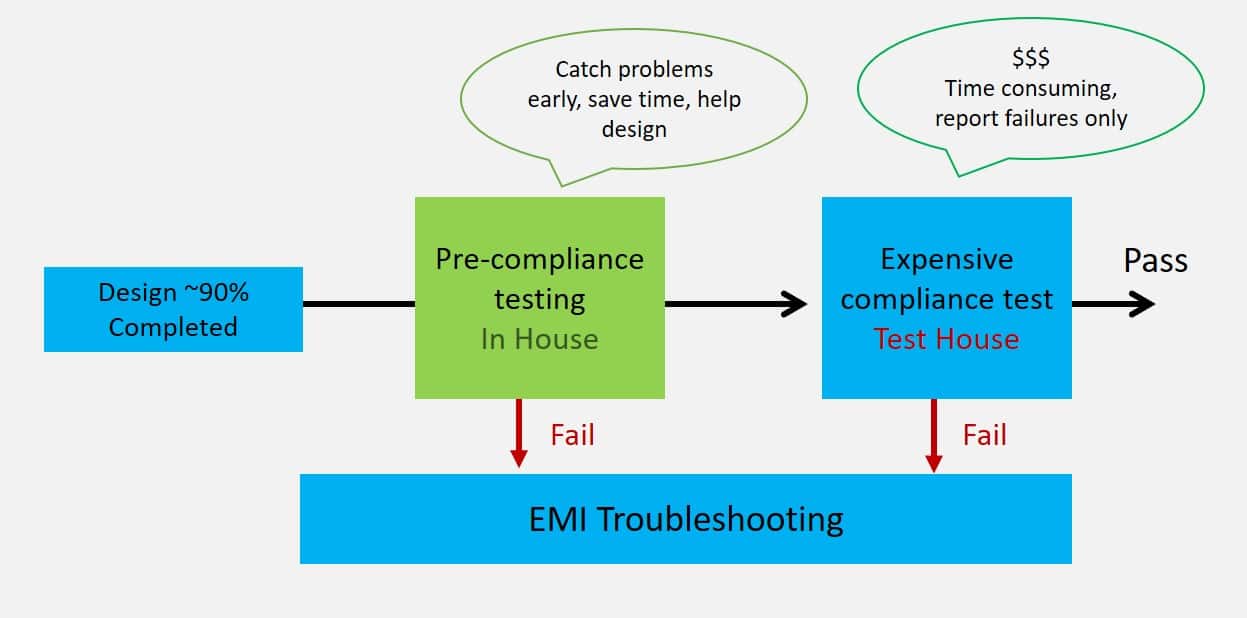
Failing EMI/EMC compliance testing can be among the design engineer’s worst nightmare. Costs and time delays add up quickly, whether it’s additional compliance and external lab testing costs, debug engineering time or in some cases unexpected board spins. To avoid these scenarios, a growing number of design teams—even those working on limited budgets—are developing their own in-house labs for conducting EMI troubleshooting and pre-compliance testing. As shown in Figure 1, such capabilities enable them to characterize and mitigate problems before heading to the third-party test house for emissions testing.

But is putting together an EMI lab really worth the time and effort involved? To answer that question, we’ll first take a look at the costs involved with EMC compliance testing when in-house testing is not available and then look at how the latest real-time spectrum analyzers and RF-capable oscilloscopes coupled with dedicated software are making this job fast and easy, even for non-EMC experts.
Typical Costs
When calculating EMC/EMI compliance test costs, a number of factors come into play. These can include the type of product, the number of countries, the number of trips to an external test house, design and debug time, the number of boards involved, and certification test cost. Table 1 provides an example of typical costs associated with FCC and CE compliance. The costs are not inclusive and additional expenses may exist, but this is a good start to illustrate some of the costs involved.
Table 1: An estimate of EMC/EMI compliance testing costs for FCC and CE compliance.
| EMC Cost Estimate (EMC + RF Only) | Cost Estimate |
| Certification cost | |
| · Unintentional Radiator (FCC + CE) | $5,000 – $10,000 |
| · Intentional Radiator (FCC + CE) | $10,000 – $20,000 |
| External Testing Lab | $1,000 – $10,000 per day |
| Engineering Resources (debug, design, layout, test) | $80 – $200 per hour per person |
| Board Spin if necessary (Cost/Board + Set-up Cost) | $1,000 – $15,000 |
| Total (not including Engineering Resources) | $17,000 – $55,000 |
As if those numbers aren’t daunting enough, let’s take a look at a couple of real-world scenarios:
Scenario #1: The design team has been taking products to a test house for years and uses the services of an external anechoic chamber provider to prepare for compliance. For the last two products they developed, they estimated taking 40 trips per year at a cost of $700 per half day, for a total of $28,000. In addition, they estimated the cost for full compliance testing, which involves more than just emission testing, was approximately $30,000.
Scenario #2: This team faced a major challenge as it spent a year trying to figure out where the “noise” in their product was coming from. To test the product, they went to a lab with an anechoic chamber for pre-scans at a cost of $1,250 per hour for a technician, equipment, and chamber. They went to the lab once a quarter with up to 12 boards. On some occasions, they would spend a full day. In reviewing their EMC/EMI pre-compliance expenses, they discovered they had incurred lab expenses of approximately $30,000 for the year, not to mention product delays and lost staff time. This number also doesn’t include actual certification costs.
The bad news is that these are far from isolated incidents. As product complexities increase and form factors shrink, designers need to find cost-effective ways to identify issues well in advance during product development cycles—not just before heading to production.
EMI Troubleshooting Versus Pre-Compliance Testing
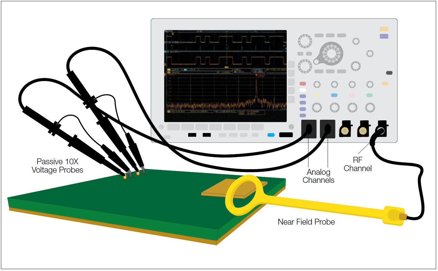
There’s a difference between general troubleshooting or debugging EMI issues and pre-compliance testing, which is important to understand when planning your own in-house EMI test kit. General troubleshooting is usually performed with a set of near-field probes or RF current probe, and a spectrum analyzer or an RF-capable oscilloscope. The goal is to identify sources of harmonic energy and determine fixes that reduce the harmonic amplitudes. Here, we’re mainly looking for relative changes. While full compliance testing procedures are designed to produce absolute, calibrated measurements, troubleshooting can be performed using relative measurements.
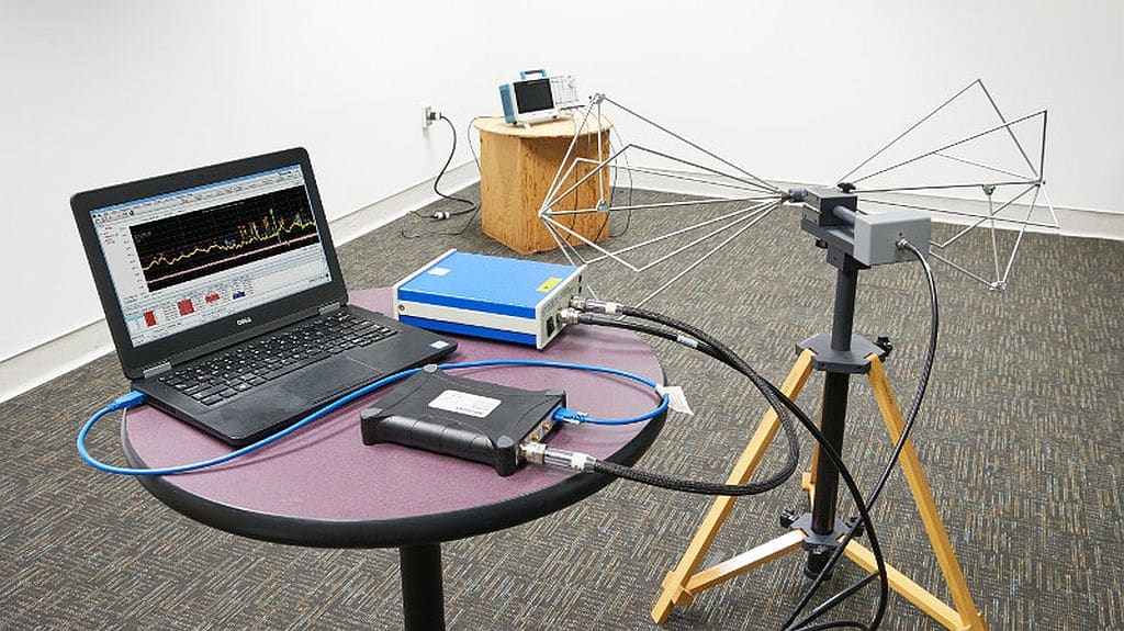
Pre-compliance testing, on the other hand, attempts to duplicate the way the full compliance tests are run to the best ability possible and to compare with actual emission test limits (Figure 2). This requires a calibrated EMI antenna, knowledge of the gains or losses in the measurement system, and emission limit tables based on the standards of interest.

For best results, the radiated and conducted emissions test is usually performed inside a semi-anechoic chamber or GTEM cell in order to eliminate outside received signals (ambient signals), such as broadcast radio, television, two-way radio, or cell phones. However, this can add considerable expense and is not always needed with modern test equipment and software tools. As a result, in-house emissions pre-compliance tests can often be set up outside a shielded chamber and techniques can be used to distinguish ambient signals from those emanating from the product under test.
For example, some spectrum analyzers with EMC pre-compliance software support making an ambient measurement of the environment while the product is turned off to give a baseline of what RF noise is present. This can then be subtracted from the actual measurement using a math trace so the user can distinguish between failures coming from the device under test and the surrounding environment.
Setting up your lab
So, what’s involved in developing a basic EMI troubleshooting and pre-compliance test lab? It’s not nearly as expensive as you might think. As noted above, pre-compliance EMC testing and troubleshooting does not necessarily require a semi-anechoic or EMC chamber, and the equipment is less expensive than full compliance test equipment.
Figure 3 shows the equipment required for radiated emissions pre-compliance testing including a calibrated antenna, preamp, and spectrum analyzer with EMC software. For conducted emissions testing, all you’ll likely need are a spectrum analyzer and a line impedance stabilization network (LISN) and optional power filter or preamp. However, by far, the most common EMC failure encountered by designers during a full EMC compliance test is due to radiated emissions.

Here’s a run-down on the equipment you’ll need to get started performing your own radiated and conducted emissions testing:
Spectrum Analyzer or RF-Capable Oscilloscope
An affordable USB-based real-time spectrum analyzer is the preferred option for this application because unlike a traditional swept-tuned spectrum analyzer, it can capture and display intermittent or infrequent signals with high precision and high probability of intercept. The real-time spectrum/signal analyzer can make measurements, using narrow resolution bandwidths (RBW), orders of magnitude faster than traditional swept-tuned analyzers, saving users time when scanning and searching for low-level RF spurs. To verify the performance of a wireless module or radio, it can also perform signal analysis such as EVM measurements and constellation diagrams to verify the quality and performance of many common wireless signal standards.
But for teams with limited budgets or who prefer to focus their testing on EMI troubleshooting, it may make more sense to consider a multi-purpose RF-capable oscilloscope that has a separate RF input coupled with an internal spectrum analyzer. The latest mixed-signal oscilloscopes also offer multi-domain capabilities beyond traditional oscilloscope FFTs, allowing independent time and frequency domain control over multiple channels. The ability to correlate signals in both domains significantly improves troubleshooting.

While an oscilloscope is very useful for determining rise times and ringing and may have built-in frequency-domain capabilities, a real-time spectrum analyzer is still the desired instrument for EMI troubleshooting and pre-compliance measurements. For pre-compliance scanning, depending on the standard, CISPR detectors for peak, avg, and quasi-peak (QP) may be needed. So, make sure your spectrum analyzer supports CISPR detectors, when necessary and to always refer to your standard(s) of interest to determine exactly what’s needed.
The frequency range required will depend on the standards and regions you will be testing for. The lowest frequency range is typically determined by the lowest frequency clock included in your design. The maximum frequency measurement range is a factor of the highest frequency generated or used in the device or on which the device operates or tunes. Table 2 shows how the FCC defines it for unintentional radiators:
Table 2. Instrument frequency range for EMI pre-compliance testing
| Highest frequency generated or used in the device, or the device operates or tunes | Upper frequency of measurement range |
| Below 1.705 MHz | 30 MHz |
| 1.705 -108 MHz | 1,000 MHz |
| 108 – 500 MHz | 2,000 MHz |
| 500 – 1,000 MHz | 5,000 MHz |
| Above 1,000 MHz | 5th harmonic of the highest frequency or 40 GHz, whichever is greater |
There are many caveats with frequency ranges depending on the type of product. For understanding this more for your exact frequency measurement range, be sure to look at FCC Part 15.33 or the specific standards you’re testing for. Important things to look for when deciding on a spectrum analyzer or oscilloscope-based solution for EMC pre-compliance testing include the following:
- Low noise floor
- Wide frequency range (to cover your measurement range)
- Peak, AVG, and Quasi-Peak detectors (similar to actual EMI receivers)
- Adjustable RBW that can go as low as 1 Hz
- Programmable interface
- Reliable and within cal
- EMC software allowing you to:
- Account for the gains/losses of accessories
- Compare traces
- Distinguish ambient signals
- Apply limit lines
- Report notes, images, and results
Antenna, Probes
For troubleshooting, you’ll want a set of near-field probes and a current probe. For pre-compliance radiated emissions scanning you’ll want an EMI antenna. The antenna you need will depend on the frequency range of your required measurement. Occasionally, you will need multiple antennas because gain profiles vary with frequency. You may not be able to see your measurement if the gain of the antenna isn’t high enough and the measured signal is hidden by the noise floor. To boost the gain, you can use an external preamplifier or RF amplifier between the antenna and spectrum analyzer.
Here are the four most common types of antennas used for EMC compliance testing and their typical frequency ranges:
- Loop: 10 kHz–30 MHz
- Biconical: 25 MHz–300 MHz
- Log periodic: 300 MHz–1 GHz
- Horn: 1 GHz–26 GHz
Line Impedance Stabilization Network
For conducted emissions measurements, instead of antennas, you use a LISN (line impedance stabilization network). A LISN is essentially a low-pass filter that is placed between an AC or DC power source and the DUT to create a known impedance (often 50 ohms) and to provide an RF noise measurement port. It also serves to isolate the unwanted RF signals from the power source.
Preamplifier
A preamplifier can help by boosting low-level signals above the noise floor and improving the sensitivity of your measurement system. Make sure it operates over your frequency range of interest and has sufficient gain. Some preamplifiers have the added benefit of having a rechargeable battery, allowing you to make measurements when a power source is not available.
Antenna Tripod
You’ll need a non-radiating tripod, preferably capable of raising, lowering, and rotating. Your particular standard may require a different kind of tripod. There’s a benefit to having a solidly constructed tripod made specifically for EMC testing if you can afford it, but you may be able to get away with constructing your own tripod out of wood and PBC piping.
Coaxial Cables
You’ll need two RF cables. One for connecting between the antenna and preamplifier and one for connecting between the preamplifier and spectrum analyzer or oscilloscope. They don’t need to be very expensive. As long as they operate over the frequency range you need, match the impedance of your antenna, and are stable while being bent you should be good. Cable lengths typically vary between 1 m, 5 m or 10 m.
Turntable
You’re going to need to position your device or equipment under test in various angles depending on the EMC standard. Turntables designed for EMC testing can be purchased to allow easy and precise rotation. For those on a budget, a cardboard box positioned at the correct height and distance is a cost-effective alternative.
Test environment
Unlike full EMC/EMI compliance testing, pre-compliance testing does not necessarily require compliant test equipment or anechoic chamber. Today you can make relatively accurate results in your own office environment, conference room, or basement. While an actual chamber is ideal, you can usually get along fine without it and save 10s or even 100s of thousands of dollars. However, when in very noisy environments, low-cost pre-compliance RF enclosures or TEM cells can be used as well.
When selecting a test site, it is best to pick a location that will minimize external signal sources. Rural areas, conference rooms or basements are good because they minimize signals that might mask the DUT emission levels you are trying to measure. Other considerations for improving accuracy involve having a good ground plane and reducing the number of reflective objects around the test area. You can also implement measurement techniques which involve making a baseline ambient noise measurement, as mentioned earlier.
Conclusion
An in-house pre-compliance EMC/EMI test solution can help you pass full compliance testing, saving you considerable time, frustration and expense, particularly when you test early in the design cycle when problems can be identified and mitigated relatively easily. Developing in-house EMC pre-compliance and troubleshooting capability can be done cost effectively, especially in comparison to the cost of multiple trips to the test house. And, unlike full compliance testing, pre-compliance testing does not necessarily require expensive compliant test equipment or an anechoic chamber.
References
- EMC Test Lab Guide — https://emcfastpass.com/emc-testing-beginners-guide/emc-test-lab-guide/
- The Financial Case for an EMI/EMC Pre-Compliance Test Solution – https://www.tek.com/blog/financial-case-emi-emc-pre-compliance-test-solution
- Electronic Code of Federal Regulations, e-CFR data is current as of September 25, 2019, Title 47, Chapter I, Subchapter A, Part 15, Subpart A, §15.33 — https://www.ecfr.gov/cgi-bin/text-idx?tpl=/ecfrbrowse/Title47/47cfr15_main_02.tpl
- Low-cost EMI Pre-compliance Testing using a Spectrum Analyzer — https://www.tek.com/document/application-note/low-cost-emi-pre-compliance-testing-using-spectrum-analyzer
- Conducted and Radiated Emissions Testing Application Note – https://info.tek.com/www-conducted-radiated-emissions-testing-app-note.html?_ga=2.7789618.1818033532.1565629341-217846865.1564189683
- EMI Pre-Compliance Testing and Troubleshooting with Tektronix EMCVu https://www.tek.com/document/application-note/emi-pre-compliance-testing-and-troubleshooting-tektronix-emcvu
- EMI Troubleshooting with Real-Time Spectrum analyzers – https://interferencetechnology.com/emi-troubleshooting-with-real-time-spectrum-analyzers/
- Practical EMI Troubleshooting
- Assembling a Low-Cost EMI Troubleshooting Kit – Part 1 (Radiated Emissions)
