To design effective filters we must maximize impedance discontinuities, at the frequencies of concern for emissions and/or immunity. Capacitors are used in conjunction with the RF Reference Plane (see Figure 1) to create low impedances, applied in shunt, whilst resistors or inductors are used to create high impedances, applied in series.

When the source and load impedances seen by a current (DM or CM) are both low – also taking into account the impedances of their current loops including their return paths – a ‘Tee’ filter (with either R or L) is preferred. When the source and load impedances seen by a current (DM or CM) are high – also taking into account the impedances of their current loops including their return paths – a π (‘Pi’) filter (with either R or L) is preferred. When the source impedance for a current (DM or CM) is low, and its load impedance is high (or vice-versa) – also taking into account the impedances of their current loops including their return paths – an RC or LC filter (with the R or L connected to the low impedance side) is preferred.
For low-power circuits with low-frequency wanted signals and high impedance loads, it is often possible to replace the inductors in these simple circuits with resistors of between 100Ω and 10kΩ to save cost and even sometimes achieve higher attenuations over wider frequency ranges.

When the source impedance of the noisy current (DM or CM) to be filtered is low, fitting a simple C filter will increase the noise currents flowing in the circuit, increasing H field emissions, and will also increase the noise voltages across the circuit’s 0V plane, increasing its CM emissions. Preventing DM or CM noise currents from increasing is another reason why we always follow a low impedance source with a series resistor or soft ferrite choke (to create an RC, LC or Tee filter).
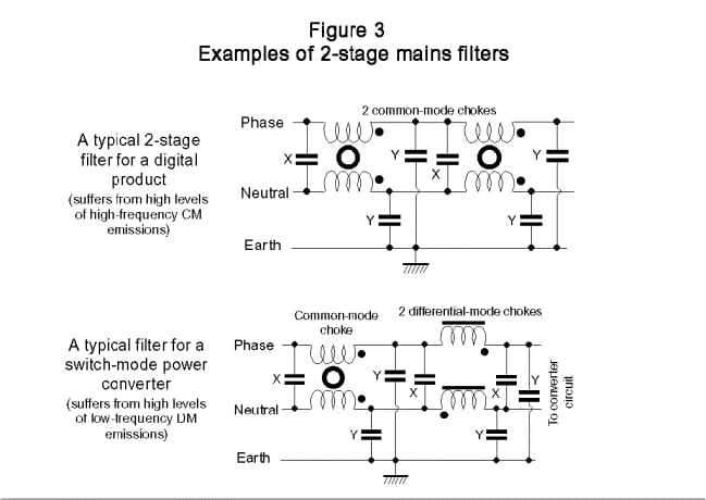
For balanced (differential) signals the RF Reference in Figure 2 is replaced by the return conductor for the conductor pair – but only for DM filtering. For CM filtering we need two circuits as shown in Figure 3 – one for the send conductor and one for the return conductor, both of them connecting their capacitors to the RF Reference Plane. CM filtering can also benefit greatly from the use of ‘CM chokes’ — which will be described in a later post.


