Read Part 1 of this CubeSats series here
In 2016 and 2018, Bob Vermillion gave a series of groundbreaking presentations on “CubeSats Require ESD Handling Protocols for Launch & Space Survivability” to enthusiastic audiences of university graduate students, aerospace engineers, NASA civil servants and academic researchers at the NASA-Auburn Academy of Aerospace Quality Workshop, Huntsville, Alabama and NASA Quality Leadership Forum, Cape Canaveral.
This article will discuss steps of evaluation for electrostatic discharge (ESD) integrity that support small spacecraft survivability in space by utilization of sound ESD testing procedures.
What project classification can NASA researchers and industry utilize in CubeSat builds for NASA compliance?
As several CubeSat projects have been known to be built on an office desk, the author will outline what is an acceptable practice to safely stage, assemble, package and transport small spacecraft projects.

The reader can observe the structural elements (Figure 1) that make up the deployment cylinder and TubeSats plus flight hardware.
The deployment cylinder or TuPOD serves as a launch platform and is spring-loaded with two TubeSats. Uniquely formulated by Amin Djamshipour, Teton Aerospace, the TuPOD engineered material was additive manufactured at NASA Ames Research Center.
A TuPOD should minimize Triboelectrification (charge generation) and shield against ESD when launching TubeSats in space (e.g., the ISS) from a deployment cylinder at 0% relative humidity (RH).
A TubeSat system ensures that circuit card assemblies (flight hardware) are not killed by field-induced discharges in Low Earth Orbit (LEO) and beyond.
One cannot overlook ESD procedures. The reader will learn what practices are acceptable for the CubeSat engineer and scientist.
Adherence to sound ESD shielding packaging protocols is critical during test, inspection, transport and handling of CubeSats susceptible to ESD damage.
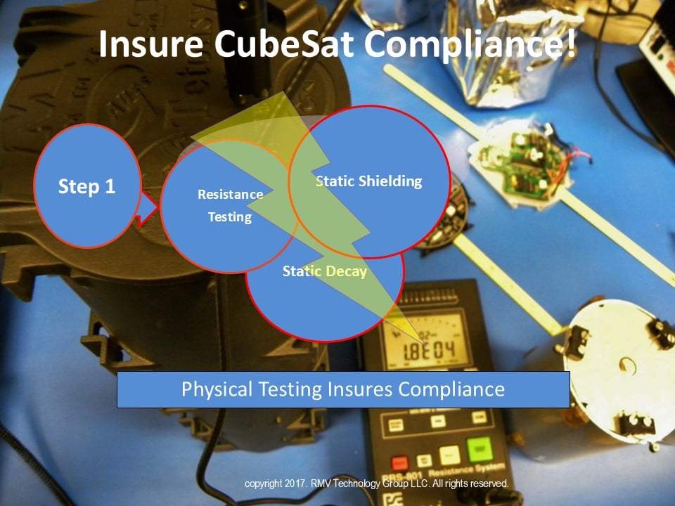
CubeSat Evaluation Methods for Static Control Integrity (Figure 2):
- Protocols following NASA-STD-8739.6B, Section 7 that call out ANSI/ESD STM11.11; STM11.12; STM11.13 for resistance is the first step in measuring the prototype deployment cylinder for ESD Integrity at 0% RH to qualify SmallSats for Space.
- Resistance testing is followed by electrostatic decay testing (MIL-STD-3010C, Method 4046, Modified) to ensure electrical continuity from loaded (seated) TubeSats when locked into a deployment cylinder keeping both at the same potential.
- Measuring charge is critical when TubeSats separate from a deployment cylinder to determine risk of a potential field induced discharge.
- Contact voltage testing of ESD-sensitive circuit card assemblies at a static control worksurface.
- Final test using Dr. Kolyer High Voltage Discharge (HVD) test determines shielding effectiveness of a deployment cylinder that protects circuit card assemblies from ESD events.
- Proper SmallSat Packaging protocols.
Resistance Testing

Surface resistance testing per ANSI/ESD STM11.11 of a deployment door requires measurement of both sides (Figures 3 and 4) for electrical conductivity.
Due to the deployment cylinder thickness, the average resistance value of the cylinder and door plus spring-loaded platform measured 8.03 x 10³ ohms.
If the product had been ESD-safe corrugated or flexible film, then <1.0 x 10³ ohms would be appropriate for compliance.

The volume resistance test consists of a concentric ring fixture with a spring-loaded platform inside the deployment door through the cylinder to a stainless-steel electrode base per ANSI/ESD STM11.12 at 2.21 x 10³ ohms (Figure 5).

Figure 6 for 2-point resistance (ANSI/ESD STM11.13) measured 1.1 x 10⁴ and 1.8 x 10⁴ ohms, respectively.
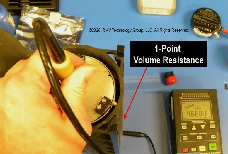
As illustrated in Figure 7, 1-point volume resistance is measured from atop the TubeSat through the second TubeSat with elevation of the first TubeSat from a stainless-steel spring platform.
Table 1 Limit: ± 1.0 x 10⁴ ohms
| Resistance Testing (Representative Results) | ||
|---|---|---|
| Deployment Cylinder | Resistance (Ω) | Constant V |
| Deployment Door (Inside) STM11.11 | 6.80E+03 | 10v |
| Deployment Door (Outside) STM11.11 | 1.00E+04 | 10v |
| Deployment Door to Cylinder Base STM11.12 | 2.21E+03 | 10v |
| 1-Point Volume Resistance from top TubeSat to Bottom TubeSat | 4.60E+01 | <10v |
| Deployment Cylinder STM11.13 | 1.10E+04 | 10v |
| Deployment Cylinder STM11.13 | 1.80E+04 | 10v |
| Average | 8.01E+03 | |
| Median | 8.40E+03 | |
| Minimum | 4.60E+01 | |
| Maximum | 1.80E+04 | |
| St. Dev. | 6.50E+03 | |
As illustrated in Table 1, resistance testing produced favorable results (±1.0 x 10⁴ ohms). The Dr. Kolyer High Voltage Discharge (HVD) test determines if resistance value equals attenuation (shielding) from ESD events during lift off from shock and vibration.
Electrostatic Decay
Again, this is a very important test method to ensure electrical continuity from the loaded (seated) TubeSats when locked into the TuPOD so that both SmallSats are equal in voltage potential.
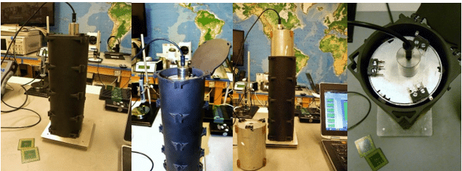
As illustrated in Figures 8-11, decay testing is conducted by placement of a closed TuPOD atop a 6-inch x 6-inch 20pF charge plate, then charged up from ±1000 volts to ±100 volts. For extreme environments, decay should occur in <0.5 seconds.
The second test is conducted from a TuPOD spring deployment platform; the third test is conducted from atop the TubeSat to the charge plate.
The last test is conducted of the second TubeSat atop the first TubeSat (Figure 12).

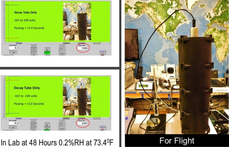

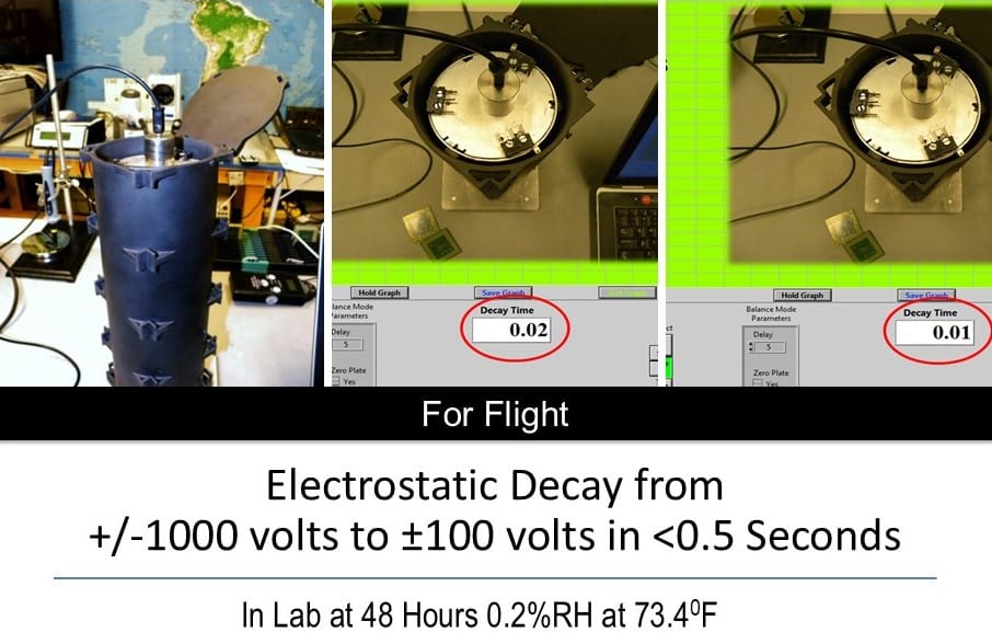
Table 2 MIL-STD-3010C, Method 4046 (Modified)
| 1000 volts to 100 volts | -1000 volts to -100 volts | ||||
|---|---|---|---|---|---|
|
Decay |
Seconds |
Start V |
Decay |
Seconds |
Start V |
| Closed TuPOD | 0.06 | 1000v | Closed TuPOD | 0.06 | -1000v |
| Spring Platform | 0.01 | 1000v | Spring Platform | 0.01 | -1000v |
| 1st TubeSat | 0.01 | 1000v | 1st TubeSat | 0.01 | -1000v |
| 2nd TubeSat | 0.02 | 1000v | 2nd TubeSat | 0.02 | -1000v |
| Average | 0.03 | Average | 0.03 | ||
| Median | 0.02 | Median | 0.02 | ||
| Minimum | 0.01 | Minimum | 0.01 | ||
| Maximum | 0.06 | Maximum | 0.06 | ||
| St. Dev. | 0.02 | St. Dev. | 0.02 | ||
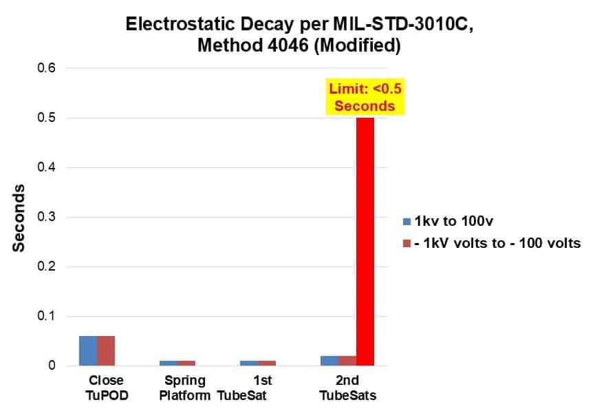
This test method clearly illustrates the actual decay from ±1000 volts to ±100 volts. The limit for acceptance shall be no more than 2.0 seconds per MIL-STD-3010C, method 4046 (modified), however, a limit of <0.5 seconds represents a more realistic limit for spacebound materials.
Triboelectrification Measurements are Critical for TubeSat Separation From the TuPOD
The Vermillion Test Method™ constitutes a trade secret to ensure spacebound materials do not pose an issue in space from friction when deployed from a TuPOD.

TuPOD & TubeSat vibration (5 minutes) was conducted at 5% RH, 73.10F. Peak voltages (-20 and -155 volts) measured within the limit of acceptance for spacebound flight hardware undergoing shock and vibration during liftoff.
Contact Voltage of ESD-Sensitive Circuit Card Assembly at Static Control Worksurface

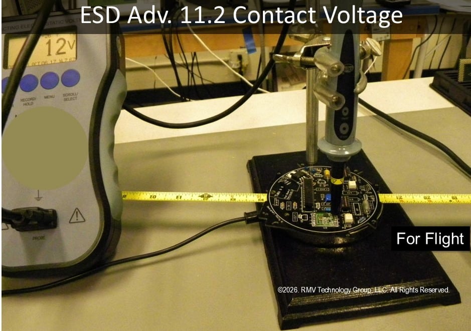
The Contact Voltage Test will not damage a circuit card assembly due to the use of an application-specific contact probe to prevent ESD events.
By special invitation from NASA in 2024, the author presented his findings for risk to flight hardware at the NASA QLF, Cape Canaveral and the NASA Safety Center that proved today’s ESD Sensitive (ESDS) devices can be killed when a static control workstation becomes charge-generating due to isopropyl alcohol cleaning in low humidity.
Moreover, worksurfaces can dry out, or fluorescent lights can cause some ESD-safe worksurfaces to lose resistance values. NASA’s limit for worksurface charging is <±200 volts.
Contact peak voltage of the TubeSat circuit card assembly measured 13.489 volts and -4.978 volts, respectively.

The test plan as above illustrates how the TuPOD and TubeSat assembly were not compromised during this build.
Final HVD Test
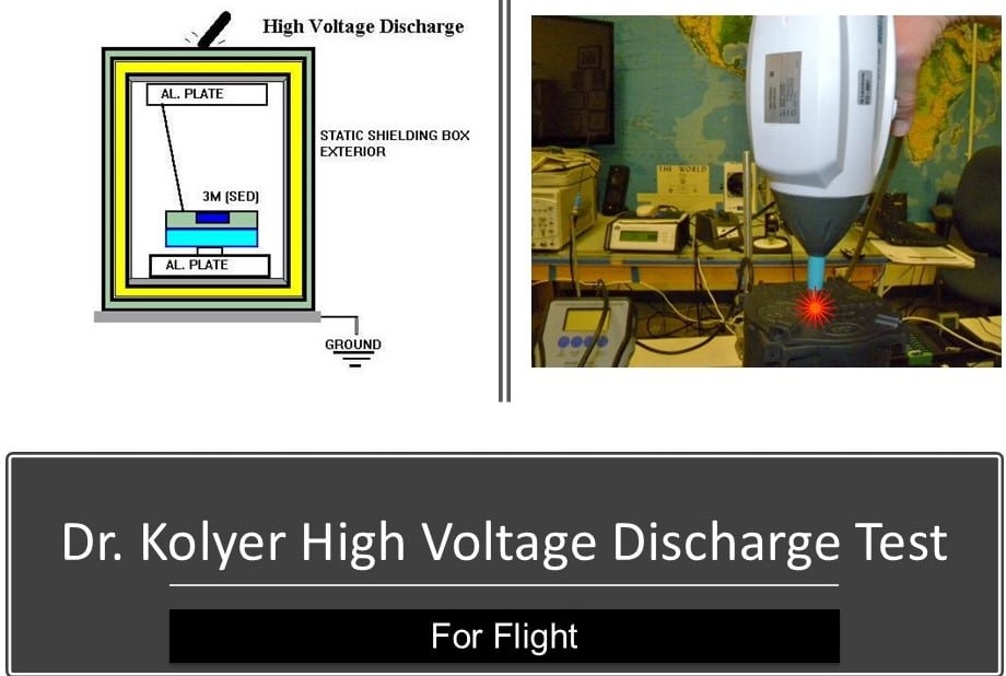
Final testing of the Dr. Kolyer High Voltage Discharge (HVD) Test determined Shielding effectiveness of the Deployment Cylinder That Protects Circuit Card Assemblies from ESD Events.

A lab-grade simulator makes intimate contact with the closed TuPOD for 10 discharges at 5kV per position. Inside the deployment cylinder, a 100-volt ESD event detector was placed inside the TuPOD (Figure 22).

After a series of 5kV high voltage discharges, no static event detector (SED) units were triggered. All passed. This finding confirms that surface resistance values were sufficient to ensure attenuation from ESD events.
Packaging Protection
The author designed a protective shielding packaging as a satellite shroud for both ESD and EMI/RFI shielding (Figure 24), first envisioned by the author.
Finally, a Vermillion TuPOD ESD corrugated container™ was innovatively designed for protection from high voltage discharge and cushioning from shock and vibration (Figure 25).


In short, the testing results were as follows:
- Deployment Door Volume Resistance passed
- Tube 2-Point Resistance passed
- Electrical Continuity Resistance from TuPod Unit to Base Electrode passed
- Volume Resistance from Deployment Door to Base passed
- Electrostatic Decay from Top to Bottom passed
- Electrostatic Decay from Both TuPod Units to Base passed
- Electrostatic Decay from TuPod Unit, Spring and Base passed
- Triboelectrification (Charge by Friction) passed
- Contact Voltage of Flight Hardware passed
- Kolyer High Voltage Discharge Shielding Test passed
Acknowledgements:
- Gompf, Ph.D., P.E., NASA Kennedy Space Center (Ret.)
- John Kolyer, Ph.D., Research Scientist, Boeing (Ret.)
- Amin Djamshidpour, Co-Founder Teton Aerospace
- Gene S. Monroe, MSEE, NASA Langley (Ret.)
- NASA Images