The way in which SPDs are connected can have a large impact on the overall protection provided
Bryan Cole
Introduction
Surge protective devices (spds) or transient voltage surge suppressors (TVSS) are used to reduce the impact of overvoltage transients on the electrical distribution networks found in various industries. Of course, the efficacy of these devices will affect the overall protection of the distribution network; how these devices are connected can have a large impact on the overall protection provided by an SPD.
Different types of configurations are used to connect SPDs to the electrical distribution network. The first is a parallel connection, which is commonly referred to as a one-port configuration. The second type is a series connection, which is referred to as a two-port configuration. There is also a type of configuration that is called a “Kelvin connection.” The configuration of a Kelvin connection is very similar to that of a two-port connection, but with small differences that will be explained.
Transient Parameters
Overvoltage transients are generated by a number of sources. These include natural events, such as lightning and electrostatic charge buildup, and man-made sources including utility switching surges, the opening of overcurrent protective devices, or the energizing or collapse of motor loads. Overvoltage transients vary considerably from event to event. Some transients are quite brief, while others are characterized by long durations. In general, all transients have fast rise times in comparison to the currents of AC electrical power. While overvoltage transient waveforms vary, there are some standard waveforms developed by the Institute of Electrical and Electronic Engineers (IEEE) that have been used for many years to evaluate SPDs.1 SPDs that have been evaluated using these waveforms have performed well in protecting electrical distribution networks.
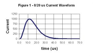
Of the standard waveforms, the most common transient used to evaluate SPDs is the 8/20 µs current waveform. The 8/20 µs current waveform is an exponentially decaying transient with a rise time of 8 µs and a duration to one-half peak of 20 µs. A graphical representation of the 8/20-µs current waveform is shown in Figure 1. The 8/20-µs current waveform has a fast rise time and a medium duration time.
One-Port SPDs
A port TVSS (or SPD) is defined as “an SPD having provisions (terminals, leads, plugs) for connection to the AC power circuit, but no provisions (terminals, leads, receptacles) for supply current to AC power loads.”2 A one-port connection is a parallel connection. Figure 2 shows a one-port or parallel-connected SPD. In this connection type, there is just one conductor per mode. In this example, only the line and neutral conductors are shown, but an all-mode, three-phase wye system would require that all modes be connected to the electrical distribution network using conductors for line 1, line 2, line 3, neutral, and ground.

There are advantages and disadvantaging associated with using a one-port SPD. The main advantage of a one-port SPD is that it is connected in shunt with the load. Consequently, the SPDs:
- Are independent of the steady-state current rating of the supply.
- Are independent of the steady-state and short circuit current rating of the load.
- Can utilize separate overcurrent protection from the load.
- Can be serviced without removal of electrical power to the load.
A one-port SPD is typically connected to electrical distribution at the service entrance or the distribution panels. Article 285.6 of the National Electric Code requires that all SPDs must have a short circuit current rating that is equal to or greater than the point of application.3 To meet this requirement, a one-port SPD can be connected through a circuit breaker or fuse that provides proper overcurrent protection.4
The SPD is in parallel with all other loads on the same panel, which makes it one of many, so the only current drawn by the SPD is the current required to power indication circuitry—as well as the currents from any parasitic parameters of the overvoltage protection components. For most one-port SPDs, the current draw is less than 3 A per phase. Therefore, the SPD is connected to a specific breaker based on the conductor size required to meet the installation needs of the circuit breaker and the SPD, both of which are identified in the product installation manuals.
Because the SPD is connected in shunt with the load, it can be de-energized to allow for maintenance without removing the electrical power from the load. This option ensures that the load will remain operational regardless of the operational status of the SPD.
The main disadvantage of the one-port connected SPD is that the lengthy leads for the conductors can give rise to impedance that reduces the amount of protection provided by the SPD. The function of the SPD is to reduce overvoltage transients by diverting current. If this reduction is accomplished using voltage-limiting components, e.g., metal-oxide varistors (MOVs), a let-through voltage of the SPD is created. For those devices that are applied in the U.S., Underwriters Laboratories (UL) issues a suppressed voltage rating (SVR) that is similar to the let-through voltage of the SPD.4 The SVR of the SPD can be used in determining the overall protection level of the installed SPD. Referring to Figure 2, the let-through voltage is identified as VSPD.
Once the overvoltage protection characteristics of the SPD are known, the voltage drop resulting from the conductors used to connect the SPD to the network must be determined. In Figure 2, the conductors are identified as VL.
The conductors that connect the SPD to the electrical distribution have resistive, inductive, capacitive, and conductance parameters. For most cases, the essential parameter of concern is inductance.
The let-through voltage of the SPD and the connecting wires is calculated by:
where
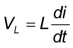
VSYS is the let-through voltage of the SPD plus that of the associated conductors, VSPD is the let-through voltage of the SPD, and VL is the voltage brought about by the conductor’s inductance. The voltage resulting from the conductor’s inductance can be determined by:
where
L is the inductance of the wires, and di/dt is the change in current with respect to time. The total inductance of the conductors is determined by their length and the geometrical configuration.6 For standard wire configurations that consist of one conductor for each phase, neutral, and ground mode, the voltage drop as a result of inductance is 144 V per meter per 1000 A of 8/20-µs current.
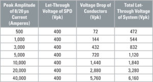
Using a common SVR for SPDs designed for 208Y/120 VAC, 3-phase wye systems of 400 Vpk, the let-through voltage using Equation 1 can be determined for a number of surge currents (Table 1).
As this example shows, with only 500 A of transient current, the SPD and the associated conductors provide a let-through voltage to the load of 472 Vpk. This will provide adequate protection for most loads. As the peak amplitude of the current increases beyond 3000 A, the let-through voltage is determined largely by inductance caused by conductor length rather than the performance attributes of the SPD. As the transient current is increased to 40,000 A, the let-through voltage of the connected SPD is not providing any protection as the breakover voltage of the electrical distribution of a facility is approximately 6000 V.1
Two-Port SPDs
A two-port SPD is defined as “a TVSS (SPD) having provisions (terminals, leads, or plugs for connection to the AC power circuit and provisions (terminals, leads, or receptacles) for supplying current to one or more AC power loads.”2 A two-port SPD is a series device, which must have the capacity to transmit the rated current from the source to the load.
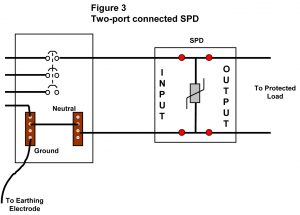
Figure 3 shows a two-port connected SPD. The two-port SPD connection type has specific input and output terminals for every mode of protection provided. In this example, only the line and neutral conductors are shown, but in an-all mode, three-phase wye system that requires all modes to be connected to the electrical distribution network, line 1, line 2, line 3, neutral, and ground conductors are required.
There are advantages and disadvantages associated with using two-port SPDs. The two-port SPD is connected in series with the load. This coupling means that the SPDs:
- Are dependent on the steady-state and short circuit current of the AC supply.
- Are dependent on the steady-state and short circuit current of the load.
- Utilize the same overcurrent protective device as the load. The load must be removed from the source of supply to service the SPD.
The main advantage with the two-port SPD is the voltage protection offered to the load. Similar to the one-port SPD, the two-port SPD obtains an SVR from UL. However, because the conductors that are in series with both the SPD and the load, the additional voltage generated from the inductance of the conductors is eliminated. Therefore, for the 8/20 µs currents detailed in Table 1, the let-through of the SVR remains at 400 Vpk.
Article 285.6 of the National Electric Code (NEC) requires that the SPD have a short circuit current rating that is equal to or greater than the point of application.3 For a two-port SPD, it must also have a withstand rating that is equal to or greater than the short circuit current rating.2
The disadvantages of the two-port SPD are associated with its series connection with the load. Because of the series connection, the SPD must be capable of supplying the rating current without overheating. If inductive components are used in series between the input and output connection, then these components must be sized so that they can handle the rated load current over the specified operating temperature range of the SPD.
Because the two-port must be capable of supplying full load current, it must also meet the requirements for a conductor bending radius inside the enclosure of the SPD.3 This typically makes the two-port SPD larger than an equivalently rated one-port SPD.
Finally, if the two-port SPD must be serviced, the load must be turned off, or a bypass switch needs to be installed. The inability to perform periodic maintenance or checks on the SPD without cutting off power to the load can be detrimental to some applications.
Kelvin-Connected SPDs
Kelvin-connected SPDs are very similar to two-port SPDs. The term “Kelvin Connection” comes from the instrumentation field. A Kelvin Connection is a methodology used to obtain a precise measurement of DC voltages from distant locations.7 When measuring DC resistance from a distance, there is a considerable voltage drop associated with the conductors used for the meter. To measure the resistance of a distant device, four wires are used. One set of wires from a constant current source is used, while a second set of wires is used for the voltmeter. Because the resistance of both sets of wires is the same, the error in measurement due to the conductors can be determined and then removed using a summation circuit.7 The four-wire method is known as the Kelvin Connection.
How does the Kelvin Connection relate to SPDs? Simply, a Kelvin connected SPD is a two-port SPD that has no series impedance between the input and output terminals (Figure 4). As the reader can see, there is virtually no difference in the placement of the terminals for the input connection and the output connection of the Kelvin-connected SPD.
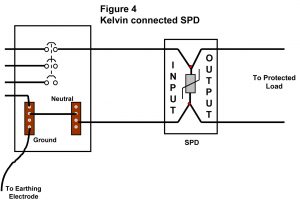
A Kelvin-connected SPD has the same advantages and disadvantages as a two-port SPD. The primary advantage of the Kelvin Connection is the lower let-through voltage of the installed SPD arising from the fact that a conductor does not contribute additional voltage from the conductor’s inductance.
As to a disadvantage, the SPD is connected in series with the load. The SPD must be capable of transmitting the required current from the source to the load. Because there is no series impedance, the SPD will not have the same temperature problems caused by heat-producing components that are typically associated with two-port SPDs.
Also, like two-port SPDs, the Kelvin-connected SPDs must be provided with overcurrent protection that meets the requirements of the NEC short circuit current requirements and withstand the requirements of UL.2, 3
Because the Kelvin-connected SPD is also a two-port device, it must also meet the requirement for a conductor bending radius inside the enclosure of the SPD.3 This typically makes the Kelvin-connected SPD similar in size to a two-port SPD and larger than an equivalently rated one-port SPD.
Finally, if the Kelvin-connected SPD needs to be serviced, the load must be turned off, or a bypass switch must be installed. Again, the fact that the SPD cannot be checked and that periodic maintenance is impossible without cutting off power to the load can be detrimental in some applications.
Conclusion
Every connection methodology used to install SPDs has advantages and disadvantages. This article has outlined those related to the one-port, or parallel-connected SPD; the two-port, or series-connected SPD; and the Kelvin-connected SPD. As was shown, the one-port SPD is easier to install and maintain, but has limitations in the amount of overvoltage protection that it can provide because of the associated voltage added from the inductance of the conductor. Two-port, and Kelvin-connected SPDs do not have the added voltages caused by the inductance of the conductor.
One-port SPDs are easier to maintain and service as they are separate from the load; whereas two-port and Kelvin-connected SPDs are in series with the load. When servicing a two-port or Kelvin-connected SPD is required, a bypass switch is required or the load must be turned off. Also, two-port and Kelvin-connected SPDs are larger than equivalently rated one-port SPDs as the series connected design requires that these devices have sufficient bend radius within the enclosure to accommodate the ampacity of the load.
Depending on the application, some of the advantages may be more important than the disadvantages, or vice versa. It is important that for every application, the engineer designing the system examine the purpose of the SPD and its relationship to the load it is intended to protect for the life of the facility.
References
- Institute of Electrical and Electronic Engineers (2002). IEEE Recommended Practice on Characterization of Surges in Low-Voltage (1000 V and Less) AC Power Circuits, IEEE C62.41.2TM-2002. NY, NY USA.
- Underwriters Laboratories, Incorporated (1986). Standard for Safety, Transient Voltage Surge Suppressors. UL 1449, Northbrook, IL USA.
- National Fire Protection Association, National Electric Code®, NFPA 70-2005, Quincy, MA USA.
- B.R. Cole, K. Brown, P. McCurdy, T.E. Phipps, and R. Hotchkiss. Short Circuit Current Ratings of Surge Protective Devices (SPDs). Accepted for presentation at the IEEE PES Summer Meeting, July 2006.
- Harris Semiconductor (1998). Transient Suppression Devices and Principles. Application Note AN9768, Melbourne, FL USA.
- B.R. Cole. Voltage Drop Calculations of Various Geometrical Configurations in the Application of Surge Protective Devices (SPDs). Electrical Contracting & Engineering News, December 1999.
- T.R. Kuphaldt. All About Circuits. Retrieved January 12 2006, http://www.allaboutcircuits.com/vol_1/chpt_8/9.html.
Bryan Cole, NCE is the President of Technology Research Council. Technology Research Council provides education to the engineering field through papers and seminars and performs consulting services on various issues related to electrical power systems, technology, and product safety. Bryan has 20 years of design and product safety experience in surge protection devices (SPDs), electromagnetic interference (EMI) filters, harmonic filters, and aviation instrumentation. He a member of the IEEE, UL Standard Technical Panels for SPDs, temporary power taps, and switchgear and panel boards, and transfer switch equipment, and is a member of the U.S. National Committee to the IEC on SPDs. Bryan is a NARTE-certified engineer in Product Safety, has a Bachelor’s degree in electrical engineering from Binghamton University, a MBA from the University of Phoenix, and is a Ph.D. student at Northcentral University.


