Relevant data and basic calculations can determine the level of lightning protection needed for a particular facility.
Bryan Cole
Technology Research Council Nichols, NY, USA
Jim Tiesi
Emerson Network Power Surge Protection Binghamton, NY, USA
High-reliability systems require system up-times that approach reliability requirements of 99.9999 percent. Putting this requirement in perspective, this translates to a system that is operational for 8,759 hours, 59 minutes, and 30 seconds every year, leaving only 30 seconds of down-time for unplanned maintenance, power failures, equipment failures, etc. To meet the demands of high-reliability systems, components used in those systems must be capable of operating in numerous adverse environmental conditions. These include common environmental stresses such as temperature and humidity, as well as those stresses associated with nearby and distant lightning activity.
A majority of high-reliability systems are installed with lightning protection systems. Lightning protection systems include lightning down conductors, a multitude of earthing electrodes, equipotential bonding, and surge protective devices (SPDs). Most of the components of a lightning protection system ensure that lightning current is directed to the earth. The SPDs are needed, and are required by some codes, to ensure that damaging lightning currents are shunted from the electronic devices that monitor, control, and perform functions within the high-reliability system.1
Once the decision is made to install an SPD, one must consider the protection needs of the facility and the capabilities of the SPD. There are a number of SPD attributes that need to be considered, e.g., surge current capability, voltage protection level, short circuit current rating, maximum continuous operating voltage, and modes of protection. This article will focus on lightning currents and the surge current capabilities of the SPD.
Lightning is a phenomenon that equalizes charges between different locations within the atmosphere, and between the atmosphere and the earth. There are three types of lightning flashes: negative, positive, and bipolar. Ninety percent of the lightning flashes are negative, slightly less than ten percent are positive, and the remainder are bipolar lightning flashes.2 Lightning varies depending on a number of environmental conditions, e.g., charge build-up in the atmosphere, dielectric breakdown of the atmosphere, and surrounding structures.Since lightning flashes are variable, understanding the parameters of lightning requires the utilization of statistical data.
Negative Cloud-to-Earth Lightning
A negative cloud-to-earth lightning flash occurs when the charge of the earth is positive and the charge of the thunderstorm cloud is negative. Negatively charged lightning typically occurs year round in lower earth latitudes and during the spring, summer, and fall months in higher latitudes. Negative lightning flashes vary in the number of strokes per flash. A representation of the initial return stroke and a subsequent return stroke are shown in Figure 1.[2] The average number of return strokes in data obtained from North American studies is 4.1 return strokes per lightning flash.2 Approximately 75 percent of the lightning flashes are multiple stroke events, with 50 percent of those lightning flashes having between two and five return strokes.2 The greatest number of return strokes recorded in a lightning flash was twenty-six, which was recorded in New Mexico.2 Additional parameters of negative lightning are detailed in Table 1.2


A majority of all negative lightning flashes contain multiple return strokes. Each return stroke hits the earth at the same point. Half of all initial return strokes will have a peak current of 30 kA, with a rise time of the current waveform of 5.5 µs, and a duration of 75 µs.2 Half of all subsequent return strokes will have a peak current of 12 kA with a rise time of the current waveform of 1.1 µs and a duration of 32 µs.2 The time interval between the initial return stroke and subsequent return strokes ranges from 7 ms to 150 ms.2 During this interval, current is flowing in the lightning channel with an amplitude as high as 300 Amperes.2
Positive Cloud-to-Earth Lightning
A positive cloud-to-earth lightning flash occurs when the charge of the earth is negative and the charge of the thunderstorm cloud is positive. Positively charged lightning typically occurs during the winter months, and only in the higher earth latitudes.2 With less than ten percent of the lightning flashes having a positive polarity, they are relatively rare in nature. However, with a number of the world’s major cities located in higher latitudes, positive lightning flashes have received significant research attention recently. The characteristic parameters of a positive return stroke are shown in Table 2.2

During a positive lightning flash, there is only one stroke and the subsequent flow of DC current. Half of all return strokes associated with positive lightning have a peak current of 35 kA with a rise-time of the current waveform of 22 µs and a duration of 230 µs.2 The DC current that flows in the lightning channel after the transient current has subsided can have an amplitude of up to 300 Amperes. The DC current can flow in the lightning channel for hundreds of milliseconds.
Standards
In the U.S., there are a number of standards and guidelines that provide guidance on surge currents within a facility. Often, the information in these documents is contradictory. The most significant documents describing the transient environment of the electrical distribution network are the IEEE Guide on the Surge Environment in Low-Voltage (1000 V and Less) AC Power Circuits, IEEE C62.41.1TM-2002, IEEE Recommended Practice on Characterization of Surges in Low-Voltage (1000 V and Less) AC Power Circuits, IEEE C62.41.2TM-2002, and the Standard for the Installation of Lightning Protection Systems, NFPA 780-2004.
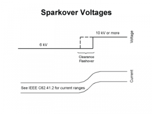
IEEE C62.41.1TM-2002 and C62.41.2TM-2002 are to be used in tandem. By referencing a number of studies, the IEEE documents provide guidance on the environmental characteristics at locations throughout a facility. The two parameters denoted are clearance voltage, or maximum open circuit voltage, and surge current as shown in Figure 2 and Table 3.3, 4


The IEEE documents detail maximum voltages on the electrical distribution system of 6 kV or 10 kV or more depending on the location. At the location from the secondary side of the power class transformer to the service disconnect, the breakover voltage is 10 kV or more. For all locations within a facility downstream of the service disconnect, the breakover voltage is 6 kV. The IEEE documents provide minimum guidance for those interested in the surge environment and do not give any firm suggestions or requirements for lightning surge current recommendations. What is provided is information on the amount of current and waveforms that should be used to test equipment located at specific locations. As the data show, 75 percent of all lightning flashes contain multiple strokes. However, none of the standards or guidelines addresses multiple strokes.
In contrast, the NFPA 780-2004 is an application standard that provides requirements of surge current for any SPD connected to the facility. For any SPD installed at the service entrance, the surge current requirement is at least 40 kA per phase using an 8/20-µs current waveform.1
Documents from these two organizations set forth different requirements. The recommended practice from the IEEE states that only 10 kA of surge current for the SPD is needed at the service entrance. The standard from the NFPA states that a minimum of 40 kA per phase is needed. While these standards may be the best available in the marketplace, their guidance or requirements remain contradictory.
Calculating Surge Current Requirements
As the data show, lightning does not have a characteristic 8/20-µs waveform. A majority of lightning flashes have multiple return strokes, and the current amplitudes range to more than 200 kA. While only a portion of the current from any lightning flash will impinge on the electrical distribution system of a facility, the designer can perform some simplistic calculations to determine how much surge current protection is need for the facility. This determination can be accomplished by calculating the surge current based on the breakover voltage, the inductance of the electrical grounding system, and the typical rise times of lightning flashes. Overvoltages from lighting systems are mainly from the inductive effects of the electrical distribution system, so Equation 1 is used.
where
V = voltage
L = inductance
di = the change in current
dt = the change in time
Using the parameters of voltage, rise time, and inductance, calculation of the surge current for the facility can be accomplished by rearranging Equation 1 to Equation 2.
where
V = the maximum voltage of the electrical distribution system
Tif = the rise time of the lightning current
L = the inductance of the electrical grounding system
I = the peak current.
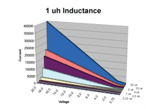
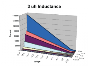
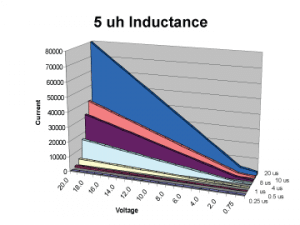
One can estimate the inductance at the service entrance of the power system. Inductances are estimated at 1 µh, 3 µh, and 5 µh. Figures 3, 4, and 5 show the peak surge currents based on peak voltages and various lightning current rise times. The x-axis is the maximum voltage of the electrical distribution system and ranges from 20,000 V to 500 V. The z-axis is the rise time. The rise times of the surge current are 0.25 µs, 0.5 µs, 1.0 µs, 4.0 µs, 8.0 µs, 10 µs, and 20 µs. The y-axis is the peak surge current and is dependent on the maximum voltage of the electrical distribution system and the rise time of the transient current.


As the rise time of the lightning currents increases, the lower the surge current from the lightning flash and the lower the amount of surge current that can flow into the electrical distribution system. As the rise time decreases, the amount of surge current that can flow into the electrical distribution system increases.
Figure 3, an impedance of 1 µh, shows that the maximum current that can flow into a facility with a breakover voltage of 20 kV and a current with a rise time of 0.25 µs is 5 kA. As the rise time of the current decreases to 20 µs, the current increases to 400 kA. If the breakover voltage decreases to 10 kV, the currents are 2.5 kA and 200 kA, respectively. While this calculation shows that 400 kA of surge current is probable, the data show that currents over 200 kA are extremely rare.
Figure 4, an impedance of 3 µh, shows that the maximum current that can flow into a facility with a breakover voltage of 20 kV and a current with a rise time of 0.25 µs is 1.67 kA. As the rise time of the current decreases to 20 µs, the current increases to 133 kA. If the breakover voltage decreases to 10 kV, the currents are 0.83 kA and 67 kA, respectively.
Figure 5, an impedance of 5 µh, shows that the maximum current that can flow into a facility with a breakover voltage of 20 kV and a current with a rise time of 0.25 µs is 1 kA. As the rise time of the current decreases to 20 µs, the current increases to 80 kA. If the breakover voltage decreases to 10 kV, the currents are 0.5 kA and 40 kA, respectively.
This technique is valid for determining the amount of current that can be injected into a facility regardless if it is a negative lightning flash with single or multiple strokes, or a positive lightning flash with a single stroke. One needs to consider the difference of the type of lightning flash and the number or return strokes when specifying the surge requirements of the surge protective device (SPD).
Conclusion
Lightning is a diverse phenomenon that consists of both negative and positive flashes. Lightning flashes have been recorded and statistically analyzed by researchers and presented in this article so that informed decisions can be made regarding the utilization of equipment for lightning protection systems. The specific parameters of a lightning flash include:
- Polarity of lightning flash
- Number of subsequent strokes in a lightning flash
- Rise time of the return strokes
- Peak amplitude of the return stroke
- Duration of the return stroke
Standards from the IEEE, the NFPA, the National Electrical Manufacturers Association (NEMA), or other organizations do not provide significant guidance on how much surge current is needed from a surge protective device (SPD) to protect a facility from lightning flashes. Using the information provided in this article, facility designers can perform a first order approximation of the surge current required from the installed SPDs. Parameters needed to perform a calculation on the current capability of the SPD are:
- Inductance of electrical distribution system earthing
- Breakover voltage of the electrical distribution system
Once the decision has been made to deploy SPDs to protect the electrical distribution system and the electrical/electronic systems within the facility, a number of SPD parameters need to be considered. These parameters are:
- Surge current capability
- Voltage protection level
- Short circuit current rating
- Maximum continuous operating voltage
- Endurance rating
- Modes of protection
In summary, lightning protection systems are vital to protect facilites from lightning damage. SPDs are an integral part of a lightning protection system and are needed to deal with transient conditions resulting from the effects of direct and indirect lightning flashes to the electrical distribution system. Existing standards do not provide sufficient guidance on the amount of surge current required. Using data and basic calculations, the facility designer can determine the levels of protection needed for a particular installation. Subsequently, the data and calculations will determine the ratings of the SPDs needed to protect the facility.
References
- National Fire Protection Association (2004). Lightning Protection Systems. NFPA 780-2004, Quincy, MA USA.
- Cole, B.R. and Buchanan, D.G. (2006). Correlating Lightning Characteristics to SPD Performance Parameters. Submitted to IEEE EMC Society for publication in EMC Transaction, Piscataway, NJ USA.
- Institute of Electrical and Electronic Engineers (2002). IEEE Guide on Surge Environment in Low-Voltage (1000V and Less) AC Power Systems. IEEE C62.41.1TM, Piscataway, NJ USA.
- Institute of Electrical and Electronic Engineers (2002). IEEE Recommended Practice on the Characterization of Surges in Low-Voltage (1000V and Less) AC Power Circuits. IEEE C62.41.1TM, Piscataway, NJ USA.
Bryan Cole is the President/Owner of Technology Research Council, and an Adjunct Professor at Lackawanna College. Bryan has 20 years’ experience in the design, development, application, and product safety of power quality equipment, aviation instrumentation, and various low-voltage distribution equipment. He is an IEEE member, serves on a number of UL Standard Technical Panels, is a member of the U.S. National Committee to the IEC, and has assisted in the development of more than 30 national and international standards related to Electrical Power Systems. Bryan is a former U.S. Marine, is a NARTE-certified engineer, holds a Bachelor’s degree in Electrical Engineering, a Master’s degree in Business Administration, and is currently a Ph.D. student in Technology Management.
Jim Tiesi is the Manager of Product Development for Emerson Network Power Surge Protection. Jim has over 12 years of experience in the design, development, and application of power quality equipment. He is active in various working groups for both the IEEE and NEMA, and is a member of the Product Development and Management Association. Jim holds a Bachelor of Science degree in Electrical Engineering from the State University of New York Institute of Technology and an MBA from Binghamton University.


