My favorite Sophomore in Engineering, Roger, and his group, made a small crane for their engineering project. It had many EMC issues. One issue they had was noise from permanent magnet DC motors. I am so glad Roger cares about this issue, because I have modeled a few permanent magnet DC motors, and I can explain how to design it so that then so they are quieter!
Motivation to Model Permanent Magnet DC Motors
The ancient brush type DC motor is ubiquitous, it’s everywhere! They are inexpensive, but noisy electrically as well as audibly. They use mechanical sliding electrical contacts to switch current through rotating coils. The contact is made by pieces of soft material called “brushes”, even though they haven’t looked like brushes for the better part of a century. As the brushes commutate, or switch the current, there is arcing. Generally, the smaller the horsepower, the more harmonics are in the motor current waveform. The more harmonics in the current waveform, the more pitting in the brushes and the commutator they slide across, and the noisier the motor. Understanding just a portion of the world of electromagnetics gives a better way to design permanent magnet DC motors.
2 Pole Permanent Magnet DC Motor Operation
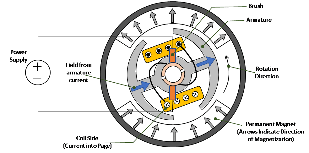
Some textbooks [e.g. 1-3] and websites [e.g. 4-5] use a very simple version of DC motors to explain their operation. A simple one coil permanent magnet DC motor is described in Figure 1. You can buy one of these simple motors at some websites such as http://www.miniscience.com/kits/Magnet_Motor_kit/ and https://www.jameco.com/Jameco/workshop/learning-center/build-dc-motor.html but they are only for demonstration since they have a dead spot which may prevent starting. Commutation (switching of the current in the motor) is too complicated to explain with a practical example. In this simple example shown in Figure 1, there are two permanent magnets attached to the thick steel case of the machine. The magnet on the top of the figure has a south pole pointing away from the armature and the magnet on the bottom has a north pole pointing toward the armature. This provides a complete magnetic circuit, shown in Figure 2. Magnetic flux in this circuit flows through the DC motor’s case, which is steel, because it must carry the flux from the permanent magnets. Current flows from a power supply through brushes made from carbon graphite, to copper commutator segments and then into the coil in the rotor (called the armature). Current in the rotor coil creates magnetic poles that produce a torque when they try to align with the magnetic poles of the permanent magnets mounted on the case of the motor. As the armature rotates, the brush bridges the space between the commutator bar segments shorting the coil connected between the segments. Coil current is reversed when the rotor continues on its journey and the torque direction is preserved. A large Ldi/dt voltage is produced at the end of commutation due to the reversal of the current in the coil, causing an arc between the commutator bars. The motor of Figure 1 is not a practical motor because it has a dead spot if the armature stops when the coil is shorted, and also has a dead short of the power supply at this point. A practical motor has more coils and commutator bars, but not necessarily more magnets.

Figure 1. One Coil Permanent Magnet DC Motor

Figure 2. Permanent Magnet Magnetic Flux Path
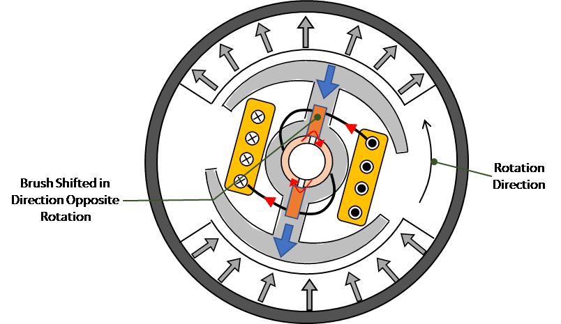
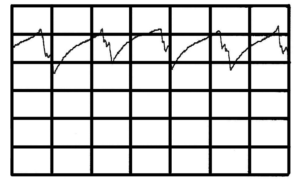
With no brush shift (a brush shift of 0 degrees is shown in Figure 1), the current in the coil decays during the short, mostly according to its L/R time constant. By the end of commutation, the current still has a long way to go to reverse to the direction of the new current input– in other words, more arcing and noise. Arcing leads to commutator and brush pitting, reducing the life of the brushes and motor. A zero degree brush shift implies that the motor coil current is switched while the field of the motor and magnet align. The line current for this condition for a motor is shown in Figure 4. A way to improve this situation is to use negative brush shift, which moves the location of the brushes in the direction opposite of rotation as in Figure 3 and waveform in Figure 4. This works by a principle of electromagnetics in which the magnets produce a voltage or electromotive force (EMF) in the moving coil. This EMF can be used to help reverse the current in the coil during the commutation. Shifting the brushes by an angle opposite to rotation direction is made so that the EMF in the coil opposes the current during the time the brush is shorted, thus helping to reverse the current and reduce the amount of arcing.

Figure 3. Negative Brush Shift: during commutation the EMF helps reverse current
Faraday’s law says that a change in the magnetic field through a coil induces a voltage in the coil. The coil has the highest EMF voltage when it is perpendicular to the magnet field (sides of the coil are under the middle of the magnets). The EMF is produced by the coil turning in the field of the magnet. Before the brush starts to short the coil, this EMF tries to stop current from going into the motor—it opposes the applied voltage. So, if the coil is shorted while the EMF opposes the current, it can be used to help reverse the current during commutation. In this position the field from the coil is partially opposing the permanent magnets.
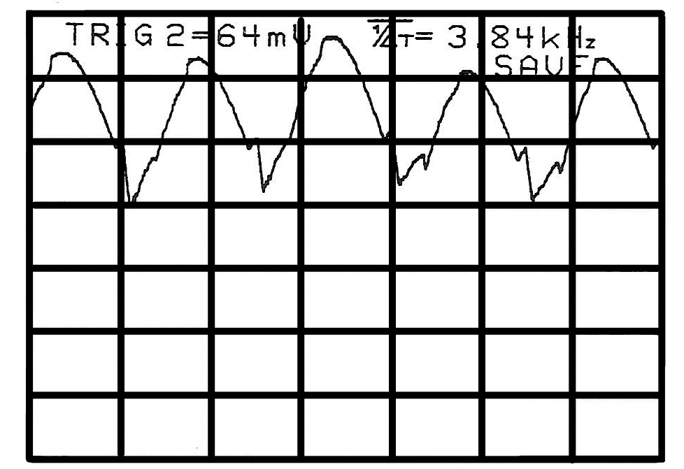
Current into the motor with a -15 degree brush shifting is shown in Figure 5. The current waveform has less of an abrupt transition during commutation due to the brush shift.

Figure 4. 0 Degree Brush Shift [Abrupt transition in current due to commutation]

Figure 5. -15 Degree Brush Shift [Smoother transition due to commutation]
Conclusion of Brush Shift Impact on Permanent Magnet DC Motor
There is an optimal brush shift that can improve commutation thus reducing arcing and current harmonic content. Normally the optimal brush shift is found empirically. It is challenging to find this point in part because it changes with the speed and load of the motor. It is possible to model the motor, predict the current waveforms, and find the point of lowest arcing [6]. A more modern technology, brushless DC motors, uses transistors to switch the current in the coils (the motor is reversed having the magnets rotating and the coils stationary). The commutation of a brushless motor can be adjusted by software to respond to load and speed. Brushless motors allow more flexibility in controlling commutation but are more expensive than brush type DC motors due to the added electronics.
Other Factors That Impact Permanent Magnet DC Motor Noise
There are many other ways to attack permanent magnet DC motor noise, but none so dramatic as brush shift. Carbon brushes are generally compounded with various alloys to increase current flow, decrease frictional coefficients, strengthen the brush, decrease the amount of commutator arcing, and lengthen the life of the brush. For example, copper and graphite are both used to increase the current carrying capacity of a brush. Graphite reduces the frictional coefficient between the brush and the commutator bars, but graphite reduces the brush life span. Copper increases the life of the brush and strengthens it, but also increases the frictional coefficient between the brush and the commutator bars. Carbon brush blends are proprietary and are a part of the motors’ black magic.
Brush angular width can also be optimized to reduce arcing [6]. Magnets are shaped to produce smoother commutation and less cogging torque. (Cogging torque is the tendency of a motor to pause when the metal the coil is wound around (the tooth) and magnets align. It influences current harmonic content. Motor teeth are also shaped to reduce cogging torque, reducing current harmonics and the resulting noise. In general, the more harmonics in the coil current, the more electrical and audible noise the motor produces through electrical coupling and through mechanical the structure. (Tune into this same channel and we will talk more about this!)
References
[1] Chee-Mun Ong, “Dynamic Simulation of Electric Machinery Using MATLAB/SIMULINK”, Prentice Hall PTR, New Jersey, 1998.
[2] Syed A. Nasar, “Electric Machines and Transformers”, McMillian Publishing Company, New York, 1984.
[3] Syed A. Nasar, “Electromagnetic Energy Conversion Devices and Systems “, Prentice-Hall, Inc., New Jersey, 1970.
[4] https://www.pc-control.co.uk/dc-motors.htm, 2013 PC Control Ltd, 30APR2018
[5] http://eblogbd.com/how-a-rotor-rotates-in-dc-motor/ , 2014-2017 eblogbd.com, 30APR2018
[6] C. R. Suriano, “A Study of DC Permanent Magnet Motor Noise Related to Line Current”, TR-EE 94-5, January 1994, School of Electrical Engineering, Purdue University, West Lafayette, IN.


