Ken Javor, EMC Compliance January 2016
(with a tip of the hat to a great performer…)
As noted in the compleat MIL-STD-461G review also found in this issue of ITEM, SAE Aerospace Information Report (AIR), AIR 6236, In-House Verification of EMI Test Equipment was written specifically to support MIL-STD-461G. Specifically, section 4.3.11 Calibration of measuring equipment has been reduced in scope to devices such as EMI receivers and spectrum analyzers, oscilloscopes and (RS103) electric field sensors. Section 4.3.11 now says, “After the initial calibration, passive devices such as measurement antennas, current probes, and LISNs, require no further formal calibration unless the device is repaired. The measurement system integrity check in the procedures is sufficient to determine acceptability of passive devices.” AIR 6236 was written to support the verification of proper operation of such devices in the EMI test facility using only test equipment commonly available in an EMI test facility. The idea behind the AIR was that if a measurement system integrity check was problematic, the AIR 6236 measurements would demonstrate whether or not there was a problem with a transducer. AIR 6236 was published in December 2015. Also, the procedures in the AIR can be used in-house to routinely self-check EMI test equipment, if desired.
This synopsis, by the AIR’s author, discusses what’s in it, and why, and includes a test procedure for one piece of equipment that was left out of the AIR.
The Introduction says that the AIR provides guidance on how to self-check the devices listed below, using equipment commonly found in EMI test facilities. The purpose is not to calibrate these devices, but to check that they have not varied significantly from manufacturer’s specifications.
The Scope says that the AIR provides guidance to the EMI test facility on how to check performance of the following types of EMI test equipment:
Current probe
Line Impedance Stabilization Network (LISN)
Directional coupler
Attenuator
Cable loss
Low noise preamplifier
Rod antenna base
Passive antennas
Power-line ripple detector (CS101 transducer)*
*The last device is not described in the AIR, but should have been, an oversight on the author’s part. The power-line ripple detector is new in the MIL-STD-461G CS101 section. The PRD allows the use of a spectrum analyzer or EMI receiver to monitor injected CS101 ripple, in lieu of an oscilloscope, which is very helpful when injecting ripple on an ac bus.
All the AIR 6236 performance checks can be performed without software. A computer may be required to generate an electronic or hard copy of data. This is not to say that custom software might not be helpful; just that the procedures as written intentionally eschew the necessity of automated operation.
The Purpose of AIR 6236 is not to reproduce the procedures used by an accredited calibration facility, but rather to provide simple and accurate methods available using only test equipment found in an EMI test facility. For simplicity, all set-ups are shown using a network analyzer, but a spectrum analyzer or EMI receiver with built-in tracking generator may be used in lieu of a network analyzer, and if that isn’t available, a separate signal generator may replace the tracking generator. The effects of these substitutions are discussed in the final section.
AIR 6236 measurement methods are not exclusive, but found to work well with a minimum of complexity. This is why it is an AIR – aerospace information report – rather than an ARP – aerospace recommended practice. There are many ways to skin the cats included in the AIR, and others may be judged better than those included, depending on the value system of the person holding judgment. The standard of value in selecting the included measurements was that they could be performed by an EMI test facility with equipment they already own and which would have NIST-traceable calibrations.
MIL-STD-461 is listed as an “Applicable Document.”
The following Performance Checks form the main body of AIR 6236.
- Current Probe
Various models of current probes based on transformer action are used from frequencies as low as 1 Hz to at least 1 GHz. All these probes may be calibrated as per Figure 1.
In Figure 1, the network analyzer source drives current through the calibration fixture, which the current probe senses. The attenuator values (excepting the 10 dB pad on the input side of the calibration fixture) are so chosen that the ratio of the current probe output (T-port) to the reference (R) input is directly the transfer impedance in dB Ohms, with no data reduction required. They also perform impedance-matching functions reducing vswr-related errors at higher frequencies. The 10 dB pad is solely for impedance matching and vswr-reducing, and need not be included if unnecessary, typically at audio frequencies where extra signal level into the calibration fixture is required. Its value does not affect the transfer impedance calculation.
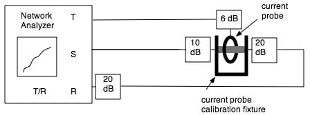
Figure 1: Current Probe Calibration – T/R ratio is the transfer impedance in dB Ohms.
At radio frequencies where there is plenty of dynamic range, the source setting should be set 10 dB below maximum in order to place 10 dB of impedance matching attenuation between the source and coaxial transmission line. Also at radio frequencies where loss in the coaxial cable becomes appreciable, the length and type of coaxial connection between current probe output and “T” port and between the 20 dB pads on the output of the calibration fixture and the “R” input must be the same.
- LISN
While there are several methods for measuring the LISN impedance specified in MIL-STD-461, none has the simplicity and ease of measuring the insertion loss the LISN presents to a 50 ohm signal source. Insertion loss is the potential measured at the LISN port relative to at a 50 ohm load. Above 1 MHz, where the 50 uH LISN approximates 50 Ohms, the insertion loss is 0 dB. At lower frequencies, insertion loss increases with decreasing frequency. Figure 2a shows the measurement set-up, and Figure 2b shows expected results, including error bars representing the MIL-STD-461 20% tolerance on LISN impedance. This method and limit account for the 0.25 uF blocking capacitor loss. Note that the upper tolerance above 1 MHz is strictly academic; there is no way the LISN impedance can be higher than 50 Ohms, so the insertion loss cannot exceed 0 dB. At frequencies where coaxial cable loss is significant, the type and length of the cables connecting to the “T” and “R” ports must be the same. The connection between splitter and LISN input power connector must be short enough to have no significant loss. Insertion loss is measured as the T/R ratio.
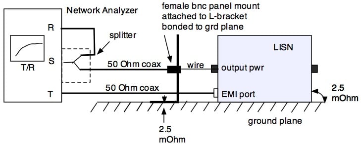
Figure 2a: LISN insertion loss measurement set-up
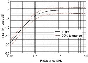
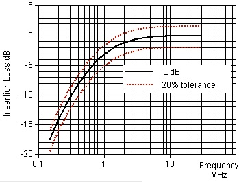
Figure 2b: MIL-STD-461 50 uH (upper curve )& 5 uH LISN insertion loss (lower curve), including losses in the 0.25 uF blocking capacitor with 50 uH curve
- Directional Coupler
The forward power port coupling factor is used in some MIL-STD-461 measurements. This procedure measures that factor, as shown in Figure 3a. The T/R ratio is the coupling port factor. At frequencies where coaxial cable loss is significant, the type and length of the cables connecting to the “T” and “R” ports must be the same.
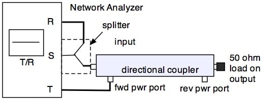
Figure 3a: Directional coupler forward power coupling factor measurement
Because return loss can be used to verify antenna performance (see section 8), the following set-up and description explain how to characterize the reverse power port. Figure 3b is similar to Figure 3a and measures the reverse power port coupling factor. The T/R ratio is the reverse power coupling port factor. At frequencies where coaxial cable loss is significant, the type and length of the cables connecting to the “T” and “R” ports must be the same. Connection between splitter and directional coupler should be as short as possible, with negligible loss.
Figure 3c shows how to determine the limit on return loss measurement associated with a good match to 50 Ohms. The return loss so measured represents a minimum vswr value that can be ascertained using this method.
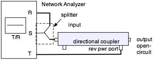
Figure 3b: Directional coupler reverse power coupling factor measurement
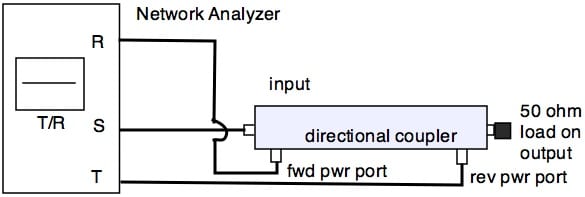
Figure 3c: Measurement to determine the minimum vswr that can be determined using the return loss method.
- Resistive Attenuator
Attenuators are used in a variety of tests, both emissions and susceptibility. This procedure measures attenuation, as shown in Figure 4. The T/R ratio represents the attenuation. At frequencies where coaxial cable loss is significant, the type and length of the cables connecting to the “T” and “R” ports must be the same. Connection between attenuator and splitter should be as short as possible, with negligible loss.
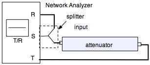
Figure 4: Attenuator measurement
- Cable Loss
Coaxial cables are used in all measurement set-ups. This procedure measures cable attenuation, as shown in Figures 5a/b. The T/R ratio represents the attenuation. The type and length of the cables connecting to the “T” and “R” ports must be the same, and for this measurement they must be measured to be the same, as in Figure 5a. Once these cables have been shown to be the same, or their differences accounted for, they may be used to measure the loss of the cable-under-test, as in Figure 5b. Because small losses are measured, vswr can be a perturbing factor. Attenuation placed between the test and reference cable can minimize any impedance discontinuity effects.
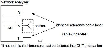
Figure 5a: Reference cable loss measurement
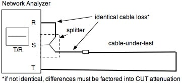
Figure 5b: Cable loss measurement
- Low noise Preamplifier Gain
Low noise pre-amplifiers are often employed to make sensitive measurements such as radiated emissions, where the noise figure performance of the spectrum analyzer or EMI receiver is in itself not good enough to measure to the required limit. This procedure measures the amplifier gain, which must be accounted for when reducing data measured using the preamplifier. Figure 6 shows the set-up. The T/R ratio represents the gain. Care must be taken to use a very low input so the amplified output is well below the 1 dB compression point of the preamplifier. This method can also be used to ascertain the 1 dB compression point, by repeatedly measuring the gain while increasing the input, until gain compression is realized. At frequencies where coaxial cable loss is significant, the type and length of the cables connecting to the “T” and “R” ports must be the same. The connection between the splitter and preamplifier should be as short as possible with negligible loss.
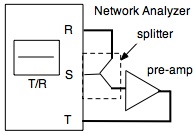
Figure 6: Low noise preamplifier gain measurement
- 41” Rod Antenna Base Transducer Factor Measurement
The base of a 41” rod antenna, whether active or passive, acts as an impedance matching device between the capacitive output impedance of the rod, and the 50 Ohm connection into the spectrum analyzer or EMI receiver. A capacitor simulating the rod output impedance must be used in series between the network analyzer 50 Ohm source output, and the point at which the rod antenna mates with the antenna base, as per MIL-STD-461F/G Figure RE102-8, and as depicted below in Figure 7. The rod antenna factor is the measured transducer factor (gain or loss) less 6 dB, to account for the half-meter effective height of the 41” rod. The ratio T/R represents the gain or loss of the rod antenna base. Care must be taken in case of an active rod antenna to select a sufficiently low source signal level in order to avoid overload of the preamplifier in the rod antenna base.
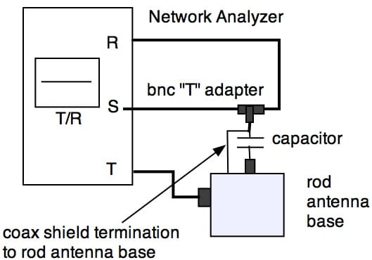
Figure 7: 41” rod antenna base transducer factor measurement
- VSWR Check of Antenna Matching Network
The most accurate check of an antenna’s performance is its physical dimensions. If the radiating elements have not suffered damage, and the matching network between the 50 Ohm coaxial input to the radiating elements is also intact, antenna performance will be as advertised. While the radiating elements may be inspected visually, the matching network cannot, and its performance must be measured to ascertain integrity. While a simple device such as the small loop used for MIL-STD-461 test RE101 may be measured with an ohmmeter to verify continuity, more complex antennas such as the biconical and double ridge guide horns cannot be so checked. A check of their match to 50 Ohms in-band to their operating frequency band can verify that the matching network is not damaged. Such a check also checks any damage to coaxial connectors.
There are many ways to measure vswr, directly and indirectly. The vswr shown in Figure 8 was specifically chosen to use only equipment found in an EMI test facility.
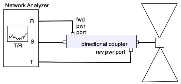
Figure 8: Antenna vswr measurement
Return loss is related to vswr as shown.
Return loss (dB) = -20 log [ (vswr-1)/(vswr + 1)]
Low vswr means a good match and return loss is high, meaning the measured T/R ratio will be low. Conversely, a poor match results in high reverse power, and the T/R ratio will be higher. In general, antennas have poor vswr characteristics near band edges, and best performance mid-band. In particular, the 137 cm tip-to-tip biconical antenna below 80 MHz has such poor vswr characteristics / high return loss as to be nearly indistinguishable from a bad balun. Therefore, vswr should be measured mid-band, and compared to manufacturer’s specifications there. Table 8 gives a range of vswr vs. return loss values useful in characterizing antenna matching networks.
| VSWR | Return Loss dB |
| 1:1 | -∞ |
| 1.22:1 | -20 |
| 1.5:1 | -14 |
| 2:1 | -9.5 |
| 2.5:1 | -7.4 |
| 3:1 | -6 |
| 3.5:1 | -3.5 |
Table 8: Vswr vs. return loss
Note that return loss at values in excess of -20 dB will be difficult to measure, and in general aren’t necessary, since they correspond to matched impedances very close to 50 Ohms, a condition not normally encountered with broadband antennas, where vswr of 2:1 to 3:1 is typical.
- Power-line Ripple Detector – not part of AIR 6236
The power-line ripple detector (PRD) acts as a resistive voltage divider and a transformer in order to allow a 50 ohm tunable voltmeter (spectrum analyzer or EMI receiver) to monitor audio frequency ripple superimposed on an ac or dc bus via the CS101 test method. The transducer factor is the constant of proportionality between the ripple potential on the bus and what is measured at the 50 Ohm tunable device. This test method uses a bnc-tee instead of a 50 ohm splitter because it is not a 50 ohm measurement, it is audio frequency, and it is critical that the reference reading be exactly what is applied to the PRD bus connection jacks. The measurement is swept from 30 Hz to 150 kHz. The PRD has two transducer factors; one is flat and represents voltage division and the transformer winding ratio, and the other rolls off above 5 kHz at the same rate but opposite slope to the MIL-STD-461 CS101 limit so that the 50 ohm tunable device measures a constant value even when the limit is decreasing with increasing frequency. This aids in making manual measurements, and also facilitates better signal-to-noise ratio as the limit gets lower at higher frequencies.
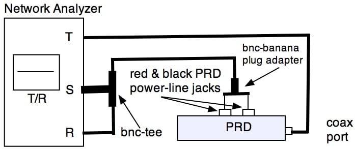
Figure 9: Power-line ripple detector transducer factor measurement
The last section is Measurement Options When a Network Analyzer Is Not Available
In lieu of a network analyzer, which is not ordinary EMI test equipment, a spectrum analyzer or EMI receiver with a built-in tracking generator may be used. If that isn’t available, a spectrum analyzer/EMI receiver may be used along with a separate signal generator.
In each case, the rf input of the analyzer/receiver replaces the “T” (test) port on the network analyzer, while the tracking generator or signal generator replaces the “S” (source) port. For those measurements involving 50 ohm devices, it is advantageous to us a 0 dBm signal source so that the lack of a reference measurement has no effect: the trace on the analyzer effectively is the “T/R” plot that would be obtained with a network analyzer.
An analyzer/receiver with the capability to display two traces may be used in the cases where the device-under-test loads the source and that must be taken into account. A sub – 1 GHz splitter such as used with a network analyzer for this purpose may be obtained for petty cash. A microwave splitter is more expensive, but still relatively inexpensive as test equipment goes.
If a tracking generator is not available, and an external signal source is used, then two options are available. Absent any controlling software synchronizing the sweep (and thus effectively creating a tracking generator) the signal source and analyzer/receiver sweep are unsynchronized, which requires placing the analyzer/receiver in “max hold” display mode and performing multiple sweeps until the observed trace has no dropouts. This requires more time than the other approaches, but requires no extra instrumentation, and no investment in computer control.
Some newer digital network analyzers are two port devices, requiring sequential measurements for reference and test measurements rather than traditional simultaneous measurements. The measurement principle is the same.
