With properly designed protection, commercial installations and buildings can be protected against each of these environments.
William A. Radasky, Ph.D, P.E., Metatech Corporation, Goleta, California, USA
Over the past five years, many publications have indicated that three unusual high-power electromagnetic threats pose significant danger to industry. These are: the high-altitude electromagnetic pulse (HEMP), intentional electromagnetic interference (IEMI), and severe geomagnetic storms caused by charged particles ejected from the sun that intercept the Earth. This increased awareness is due to several factors including a better understanding of the threat environments (and their probabilities); a better understanding of the vulnerability of modern electronic equipment, systems, and the national critical infrastructures to these environments; and the fact that the International Electrotechnical Commission (IEC) has written a collection of standards[1] to protect commercial installations from these environments. This article reviews the electromagnetic environments produced by each of these threats and follows with suggestions on how commercial installations and buildings can be protected against each of these environments.

HEMP ENVIRONMENTS
As described in IEC 61000-2-9,[2] HEMP includes the transient electromagnetic fields produced by a nuclear device detonated above an altitude of 30 km. It is noted that the HEMP peak fields decrease, but do not disappear, for burst altitudes below 30 km, and that the relative importance (magnitude and area coverage) of the three components of the HEMP varies with increases in the burst height above 30 km. Sometimes writers incorrectly use the acronym NEMP (instead of HEMP) to indicate that the environment is generated by a nuclear weapon, or they simply write EMP; in both cases the terms refer to the general category, which also includes SREMP, SGEMP, etc.[2] To describe the environment of HEMP in more detail, Figure 1 illustrates the three distinct pulses that are generated from a single detonation: the early-time (E1), the intermediate-time (E2), and the late-time (E3) HEMP. Note that each waveform in the figure is intended as a “worst case” to be used for designing protection and that under some scenarios the three pulses may be reduced in magnitude.
HEMP is of concern to commercial interests since it can cover a significant portion of a continent and may create severe problems for both unprotected commercial electronics and for the national critical infrastructure itself. Studies performed by the U.S. EMP Congressional Commission have indicated that HEMP can severely impact the electric power grid and can also affect unprotected electronics whether connected to the power grid or not.[3, 4] As confirmed by the IEC, the incident early-time HEMP creates both a high-level radiated and conducted electromagnetic environment affecting buildings, as the external wiring (power and telecom) can be exposed to the pulsed field, thus creating significant conducted voltages and currents that can penetrate into the building by way of the wiring.[5]
IEMI ENVIRONMENTS
The term IEMI has been defined as, “Intentional malicious generation of electromagnetic energy introducing noise or signals into electric and electronic systems, thus disrupting, confusing or damaging these systems for terrorist or criminal purposes.”[6] The IEC has worked intensively in this field to understand the environment levels that may be generated and the vulnerability of commercial equipment to these types of fields.[6] Additionally, researchers at recent EMC conferences have studied different aspects of the threat including the environments, the coupling, the vulnerability of equipment, and protection methods. An excellent resource for reviewing the state of the art of IEMI in 2004 is the IEEE EMC Special Issue on IEMI and HPEM. [7]
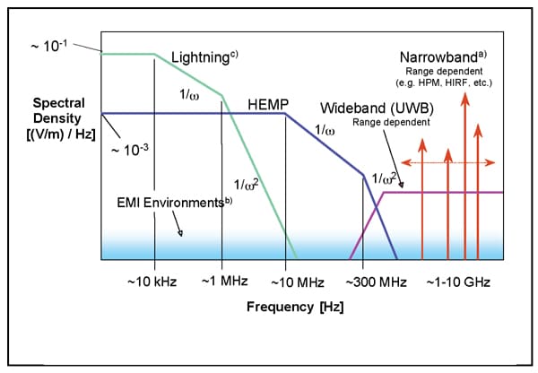
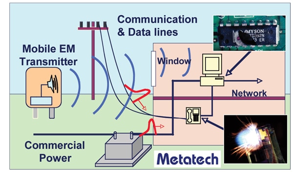
Figure 2 illustrates a frequency-domain comparison of IEMI environments with other high power EM environments, including the E1 portion of HEMP. Note that there are two main categories of IEMI environments: wideband and narrowband. The figure shows one example of a wideband environment and four different examples of narrowband environments. The IEMI frequency range of greatest interest is typically between 0.3 and 3 GHz, although higher and lower frequencies may be important in special cases.
Figure 3 illustrates a scenario of how IEMI environments can be produced and how they will interact with a building’s electronics. In this cartoon, a fiberglass van with a surplus radar system can sit in a parking lot and can generate significant fields affecting a nearby building. These fields can directly penetrate the walls and windows of the building and can couple to the wiring outside, creating voltage pulses that can then penetrate the building. Of course, other scenarios are possible including briefcase weapons taken inside the building by a visitor or by a disgruntled employee.
SEVERE GEOMAGNETIC STORM ENVIRONMENTS
The first two high-power threats and environments discussed above are man-made. There is, however, a natural environment known as a severe geomagnetic storm that has strong similarities (spatial distribution and time variation) to the late-time (E3) portion of the HEMP.[8] Given this similarity, the protection methods are also very similar. In brief, a significant increase in charged particles ejected from the sun can interact with the Earth’s magnetic field and can produce a significant distortion of the geomagnetic field at the planet’s surface. This rapid variation of the geomagnetic field (on the order of seconds to minutes) induces time-varying electric fields, which create time-varying (yet quasi-DC relative to 60 Hz) currents in a high-voltage power network. These currents induce severe harmonics and increased inductive load and heating in each exposed transformer. This can lead to the voltage collapse of the network as experienced by Quebec in March 1989. Figure 4 illustrates the contours of the B-dot environment at the Earth’s surface (in nT/min) minutes after the collapse of that power grid. The spatial extent of the “severe” fields is quite large, and the footprint can move (and has moved) further south during other storms. For additional information about severe geomagnetic storms and their impact on power grids, one should consult the literature. [9, 10]
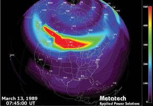
In terms of the focus of this article, the geomagnetic storm threat will affect an installation in one of two ways. If the geomagnetic storm is strong enough, the power grid voltage will collapse, and there will be a wide-area blackout. To continue operation within an installation, a backup power system would be required. Also, if the storm were very severe, it is possible that many transformers would be damaged and that the recovery time could be weeks to months (or even longer).[3] During the critical time that the power system is still operating, but after the onset of the storm (in Quebec in 1989 the power system operated for 90 seconds after the onset), power harmonics would be injected into the electric grid and would propagate into the low voltage power system. It is possible that total harmonic distortion of levels of 100 percent could occur; for this reason, some protection at the power entry point to the building is required to ensure that equipment inside is not damaged by these high levels of harmonics.
PROTECTION APPROACH FOR LOW FREQUENCY THREATS
All three of the threats described in this article may possess electromagnetic energy at or below the power frequency (50 or 60 Hz). In particular, severe geomagnetic storms and the late-time (E3) HEMP produce electromagnetic fields at frequencies below 1 Hz. These fields couple to the high, medium, and low-voltage grid producing serious operational difficulties to the power grid. There are protection concepts available to protect the power grid itself, but these are beyond the scope of this paper. Several of the high-voltage transformer protection options were reviewed and discussed by the EMP Commission in 2008.[4]
For the protection of buildings, it is important that the entry of power into the building can block high levels of power harmonics and significant switching transients, dips, and over-voltages that will occur as the power grid tries to maintain its voltage under duress. Also, the building requires a backup power source that can operate for at least one week, providing enough backup power to allow the critical aspects of the building to continue operation. This necessity means that enough local fuel for the backup must be on site because a widespread long-term power outage will likely affect the fuel transportation system (including pipelines).
Normally, the backup power system and the entry of power into a building can be designed to include a large uninterruptible power system (UPS). A properly designed UPS should be able to tolerate significant harmonic distortion (without damage), especially those that have been EMC tested by the IEC.[11] In addition, the harmonics entering the building power system should be filtered, thus reducing the threat to the internal electronics. Some testing of UPSs has indicated that they may switch to backup power early when the incoming power waveform is distorted yet still present, but this should not be a big problem unless the UPS control electronics are permanently affected by several repetitive instances of high-level harmonics over a period of minutes.
The third threat of IEMI also has a little known but important low-frequency concern for buildings. Testing the grounding system of buildings has shown that injections of 50- or 60-Hz voltages into the grounding system of a building can result in the shutdown of some of the electronics located inside.[12] Most likely, these failures are due to improper grounding of electronics within the building and the lack of a well-designed overall grounding scheme. It is possible to perform simple tests to determine the existence of this problem; however, a safer approach is to limit access to the building grounding system through the use of a security system and/or fencing.
PROTECTION APPROACH FOR HIGH FREQUENCY THREATS
Both HEMP and IEMI have substantial frequency content above 10 MHz (Figure 2). Frequencies above 10 MHz are significant since most building grounding and protection methods have been designed for EM environments below 10 MHz largely because of AM radio transmitters and nearby lightning strokes. Of course, in special cases, a location near an FM transmitter, a cellular transmitter, or radar will require special protective measures at higher frequencies. In most cases, however, this portion of the EM spectrum is usually not a threat to an entire building. There are no high-frequency electromagnetic environments associated with severe geomagnetic storms so that threat is not considered here (although GPS and other high-frequency communications from satellites can be affected by the distorted ionosphere caused by a solar storm).

In the case of the early-time (E1) HEMP, the IEC Subcommittee 77C has been developing protective measures for commercial buildings that are minimally invasive and are cost-effective. In more recent years, attention has turned to the threat of high power EM perils such as IEMI. The basic E1 HEMP protection approach consists of applying layered hardening as shown in Figure 5 from IEC 61000-5-6.[13] To determine the amount of hardening required at the room or rack level, the first step is to determine several key factors including the location of the critical electronic equipment within a facility, the amount of attenuation provided by the external facility walls (for all exposures of the building), and the immunity level of the electronic equipment to HEMP transients (both radiated and conducted).
The IEC provides a procedure for performing a simple HEMP assessment of a building using a classification system as given in IEC 61000-2-11[14] and protection concepts as described in IEC 61000-5-3.[15] After applying these, the HEMP immunity test standard, IEC 61000-4-25[16] can be used to determine actual test levels for equipment, racks, and rooms. This approach also requires consideration of the external conducted HEMP transients that must be attenuated before they reach the equipment. In most cases, the first level of conducted attenuation at the building entrance is planned to reduce but not to eliminate the HEMP or IEMI transient, unless the building includes a high-level EM shield. Additional conducted attenuation can be provided at the room or rack level. Another IEC generic standard (IEC 61000-6-6[17]) provides a shortcut procedure for determining test levels for equipment depending on their “location” in an electromagnetic sense.
For IEMI, the protection approach is similar to protecting from the high-frequency part of HEMP—with one major exception. The E1 HEMP propagates as an apparent plane wave from space, and its magnitude does not vary over a building. In the case of IEMI, the environment is produced at a point near the building, and the fields decrease with range. This issue of proximity means that the specific locations around the building available to threat weapons should be considered first in any IEMI assessment. Also, it is possible through a security process to increase secure areas and to confine would-be attackers to areas more distant from their target. Then, it is necessary to consider the size, type, and strength of available IEMI weapons, which will provide the levels of the fields as a function of distance from the source. An excellent resource for this calculation is found in IEC 61000-2-13.[6] Given all of this information, a similar approach is followed as is used with HEMP. Figure 5 is still applicable, but the fact that IEMI is a relatively new threat (compared to HEMP) means that we do not have as much experience in determining in advance the shielding effectiveness of standard building materials at frequencies in the 1-GHz range. Additionally, most equipment immunity to IEMI has not been as well established as compared to EMC or E1 HEMP, so this is an additional factor to consider.
An even more effective means of determining the levels of protection required for E1 HEMP, and/or IEMI, involves a more formal assessment process, which usually includes electromagnetic attenuation measurements from the outside to the inside of the building at the exact location of the electronic equipment. A new IEC publication to be released in the fall of 2009; IEC 61000-5-9[18] deals specifically with this process. When this process is followed, the possibilities of over- or under-hardening will be minimized.
CONCLUSIONS AND RECOMMENDATIONS
Clearly, the main resource for dealing with the protection of buildings from HEMP and IEMI are the standards and other publications produced by the IEC. Figure 6 describes the entire set of high-power transient publications, including those to be completed later this year.
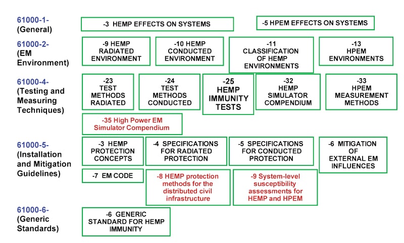
Using these publications and the basic understanding of each of the three threats discussed above, it will be possible to assess the vulnerability for an existing installation to HEMP, IEMI, and severe geomagnetic storms. With this information, a hardening plan can be developed and implemented. Test methods are also available to ensure that the hardening is properly installed and is maintained during the lifetime of the installation.
It is also important to recognize that these three electromagnetic environments are significantly worse than those encountered during the normal operation of a commercial installation; therefore, experience with the HEMP and IEMI threats are valuable commodities in ensuring that a protection job is done properly. It is recommended that those performing assessments and hardening be intimately familiar with the IEC SC 77C standards and that military standards should not be used routinely as they are most appropriate for severe, worst case situations and will be much more costly to the commercial customer.
REFERENCES
[1] Wik, M.W. and W.A. Radasky, “Development of High-Power Electromagnetic (HPEM) Standards,” IEEE Transactions on Electromagnetic Compatibility, Volume 46, No. 3, August 2004, pp. 439-445.
[2] IEC 61000-2-9, Electromagnetic compatibility (EMC) – Part 2: Environment – Section 9: Description of HEMP environment – Radiated disturbance, 1996.
[3] “Report of the Commission to Assess the Threat to the United States from Electromagnetic Pulse (EMP) Attack,” Vol. 1: Executive Report, 7 April 2004.
[4] “Report of the Commission to Assess the Threat to the United States from Electromagnetic Pulse (EMP) Attack: Critical National Infrastructures,” April 2008.
[5] IEC 61000-2-10, Electromagnetic compatibility (EMC) – Part 2-10: Environment – Description of HEMP environment – Conducted disturbance, 1998.
[6] IEC 61000-2-13, Electromagnetic compatibility (EMC) – Part 2-13: Environment – High power electromagnetic (HPEM) environments – Radiated and conducted, 2005.
[7] Special Issue on High-Power Electromagnetics (HPEM) and Intentional Electromagnetic Interference (IEMI)”, IEEE Transactions on Electromagnetic Compatibility, Volume 46, No. 3, August 2004.
[8] Radasky, W.A., J. Kappenman and R. Pfeffer, “Nuclear and Space Weather Effects on the Electric Power Infrastructure,” NBC Report, Fall/Winter 2001, pp. 37-42.
[9] Kappenman, J.G., W.A. Radasky, J.L. Gilbert, and L.A. Erinmez, “Advanced Geomagnetic Storm Forecasting: A Risk Management Tool for Electric Power System Operations,” IEEE Transactions on Plasma Science, Volume 28, No. 6, December 2000, pp. 2114-2121.
[10] Kappenman, J.G. and W.A. Radasky, “Too Important to Fail: The Looming Threats of Large Geomagnetic Storms and Other High-Altitude Disturbances with Modern Electric Power Grids May Produce Significant Damage to Critical Infrastructure,” Space Weather Journal, 18 May 2005.
[11] IEC 62040-2, Uninterruptible power systems (UPS) – Electromagnetic compatibility (EMC) requirements, 2005.
[12] Parfenov, Y.V., L.N. Zdoukhov, W.A. Radasky, and M. Ianoz, “Conducted IEMI Threats for Commercial Buildings”, IEEE Transactions on Electromagnetic Compatibility, Volume 46, No. 3, August 2004, pp. 404-411.
[13] IEC 61000-5-6, Electromagnetic compatibility (EMC) – Part 5-6: Installation and mitigation guidelines – Mitigation of external influences, 2002.
[14] IEC 61000-2-11, Electromagnetic compatibility (EMC) – Part 2-11: Environment – Classification of HEMP environments, 1999.
[15] IEC 61000-5-3, Electromagnetic compatibility (EMC) – Part 5-3: Installation and mitigation guidelines – HEMP protection concepts, 1999.
[16] IEC 61000-4-25, Electromagnetic compatibility (EMC) – Part 4-25: Testing and measurement techniques – HEMP immunity test methods for equipment and systems, 2001.
[17] IEC 61000-6-6, Electromagnetic compatibility (EMC) – Part 6-6: Generic standards – HEMP immunity for indoor equipment, 2003.
[18] IEC 61000-5-9, Electromagnetic compatibility (EMC) – Part 5-9: Installation and mitigation guidelines – System-level susceptibility assessments for HEMP and HPEM, to be published in 2009.
ABOUT THE AUTHOR
William A. Radasky received the B.S. degree with a double major in Electrical Engineering and Engineering Science from the U.S. Air Force Academy in 1968. He also received the M.S. and Ph.D. degrees in Electrical Engineering from the University of New Mexico in 1971 and the University of California, Santa Barbara in 1981, respectively.
He started his career as a research engineer at the Air Force Weapons Laboratory in Albuquerque, New Mexico working on the theory of the electromagnetic pulse (EMP) for all burst altitudes. In 1984, he founded Metatech Corporation in Goleta, California where he is currently President and Managing Engineer. During his 41-year career, he has published more than 380 technical papers and reports dealing with high power electromagnetic interference (EMI) and protection. Dr. Radasky’s current interests include studies to understand the threat of Intentional EMI and to develop mitigation and monitoring methods to protect facilities from this new threat. He is Chairman of IEC Subcommittee 77C, which is developing high-power electromagnetic protection and test standards for commercial equipment and systems. He is also the Chairman of TC-5 (High Power EM) for the IEEE EMC Society. Other IEMI activities include his roles as Associate Editor for the IEEE EMC Transactions special issue on IEMI in 2004, as Chair of the IEEE Standards Working Group to provide protection guidelines for publicly accessible computers from the threat of IEMI, and as Convenor of a CIGRE Working Group on the protection of high voltage grid control electronics from the effects of IEMI. Additionally, he served as Chairman of the IEC Advisory Committee on EMC (ACEC) from 1997 to 2008. He is an IEEE Fellow, an EMP Fellow, and a member of the Eta Kappa Nu and Tau Beta Pi honor societies. In October 2004, he was presented with the Lord Kelvin Medal in Seoul, South Korea by the International Electrotechnical Commission for exceptional contributions to international standardization.
