by Jeff Gray, Chief Technology Officer, Compliance West USA
Introduction
IEC 61000-4-5 is part of the IEC 61000 series, which describes surge immunity testing caused by over-voltages from switching and lightning transients. The second edition of IEC 61000-4-5 was released in 2005 and has been in use for many years. The third edition was released as an EN standard in 2014. The general philosophy of the third edition is unchanged from the second edition. However there have been a number of refinements to the standard: additional explanation to clear up ambiguities, new descriptions that were not included in the second edition, and new (informative) Annexes that can be used to help in the application of the standard. The purpose of this article is to outline the changes and additions that are now part of IEC 61000-4-5 3rd edition.
Critical Transition Dates
Transition from the second edition to the third edition is already taking place within the EU according to the following dates:
19 Mar. 2015 – Date of Publication (dop): The third edition has to be implemented by publication of an identical national standard by CENELEC member countries.
19 June 2017 – Date of Withdrawal (dow): National standards that conflict with the third edition must be withdrawn (i.e. the second edition can no longer be used).
Wave Shape Changes
One simple, seemingly benign addition to the third edition was to add a definition for “duration”: actually three definitions because one voltage waveform duration and two current waveform durations have been defined. This changes how the time of the waveforms are measured, and may have a significant impact on the equipment used to perform some tests. The change most greatly impacts the 8x20uS short-circuit current waveform. Figures 1 and 2 compare the measurement from the 2nd and 3rd editions of the standard. Compare T2 in the second edition to Tw and Td in the third edition.
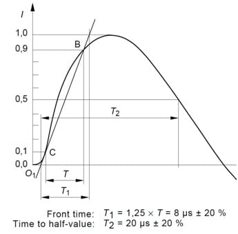
Fig. 1: waveform definition in 2nd edition (T2)
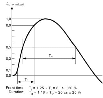
Fig 2: waveform definition in 3rd edition (Td)
Another important change to the impulse waveform is that the 1.2×50/8×20 μs wave shape must be within the limits of the standard when the impulse is applied through a Coupling-Decoupling Network (CDN); specifically the 18μF coupling capacitor. This requirement was ambiguous in the second edition: Figure 3 of the second edition shows an 8×20 μs current waveform with no CDN connected, and Table 7 in a following section describes an 8×20 waveform at the EUT port of the CDN (through the 18μF coupling capacitor). Clearly it is not possible to generate the same impulse waveform with and without the 18μF coupling capacitor in the same generator/CDN system. While the open-circuit voltage waveform is not affected, the 8×20 μs short-circuit current wave shape will be significantly distorted by the addition of the 18μF capacitor, and the peak output current will be reduced by approx. 10% (depending on the design of the impulse generator). Figure 3 illustrates the problem: the normalized short-circuit output current of a nominal impulse generator is plotted against the same generator output into a 18μF capacitor. With the addition of the 18μF capacitor the peak current is significantly lower, and the waveform duration is shorter.
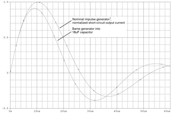
Figure 3: Normalized Short-circuit Output Current
Table 3 in the second edition seems to imply that the impulse parameters are specified not including the CDN (Figure 4). In the third edition, Table 6 is used to provide the same information, but it explicitly states that a CDN is to be included when measurements are made (Figure 5). Table 6 also includes a specification for short-circuit current when the (9μF + 10Ω) CDN is used (for line-to-ground testing). In this case, note that the short-circuit current is significantly reduced, due to the 10-Ohm resistor in the CDN.
Open-circuit peak voltage ±10 % Short-circuit peak current ±10 %
0,5 kV 0,25 kA
1,0 kV 0,5 kA
2,0kV 1,0 kA
4,0kV 2,0 kA

Fig. 4: Table 3 from 2nd ed.

Fig. 5: Table 6 from 3rd ed.
In the second edition of the standard, the 10×700/5×320 μs surge waveform is described hand-in-hand along with the 1.2×50/8×20 μs waveform. In some cases within the standard it is not clear which waveform is to be used for a particular test. This is clarified in the third edition: The 10×700 μs impulse is only to be used on external ports that connect to lines, which exit the building (more details on this point later in this article). These external lines are typically longer than 300m. The inductance and distributed capacitance of these transmission lines provide wave-shaping of any real-world transients, such that the equipment connected to the external lines sees a transient that is slower – more like the 10×700/5×320 μs waveform. Further explanation is provided in the new Annex A of the third edition.
New CDN and Calibration Requirements
This new Annex A now contains the full description of the 10×700 μs impulse, including the waveform generator, calibration of the generator, the CDN to be used, and the calibration of the CDN. In the second edition (section 6.2) only the waveform, and calibration of the waveform were described. The new Annex A does not change any requirements other than the waveform duration definition previously mentioned. However, new requirements have been added, especially relating to CDN performance.
In the second edition, calibration of the 1.2×50/8×20 μs generator was described in section 6.1.2. In the third edition this is covered in section 6.2.3, and additional details have been added. The updates provide clarification regarding the type of equipment that should be used to perform calibrations, including specifications for current transformers (if used to measure short-circuit current). Similar details have been included in Annex A regarding the 10×700 μs impulse waveform. Section 6.2.3 also makes reference to Annexes E and G of the standard (both are new in the third edition). Annex E is quite useful, as it includes many figures that show the various waveform measurements in detail (rise and duration) for all of the waveforms.
Annex G is less useful unless one has an advanced degree in mathematics. The purpose of Annex G is to point out the fact that it can be quite difficult to make accurate measurements of single-shot, high frequency events. A common example that may be more familiar to the reader is the calibration of a typical 10x oscilloscope probe. The usual method to adjust the probe is to connect to a square-wave generator, and adjust the capacitance of the probe while observing the waveform on the oscilloscope (usually a screwdriver slot is provided on the probe to make the adjustment). The probe is adjusted so that the wave shape looks “square”: the rise time is as fast as possible with minimal overshoot, or ringing, on the front edge.
Clearly a probe that is not adjusted properly, or a probe-scope combination with a low (poor) frequency response can cause an impulse voltage or current waveform to appear different on the oscilloscope screen than it actually is. So in layman’s terms, Annex G could be summarized as follows: “When measuring impulse waveforms for calibration, make sure that your measurement instruments can capture the true waveform and do not distort the results”. Fortunately Annex G is only a recommended practice (informative), not a requirement (normative).
CDN’s have become a bigger part of the 61000-4-5 standard in the third edition. The flowchart that is used to select particular CDN/test configurations has been updated to reflect newer test practices. Figure 6 shows the flowchart from the second edition; figure 7 shows the same flowchart from the third edition. Additional figures have been added in the third edition standard, which show new test setups, and at least one test configuration (Fig. 13, 2nd ed.) has been eliminated. It is important to carefully study the new test setups to ensure compliance with the third edition.
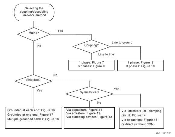
Figure 6: CDN selection flowchart from second edition
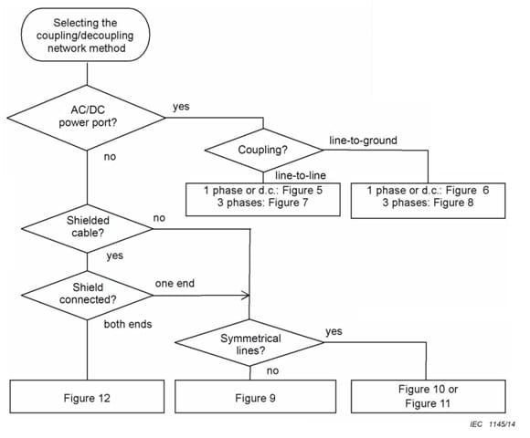
Figure 7: CDN selection from third edition
The third edition adds a peak voltage specification at the EUT port of the CDN (Table 4). The voltage tolerance varies based on the current rating of the CDN. Both the old and new standard include a tolerance specification for front time and waveform duration (Table 6, 2nd; Table 4, 3rd) but the tolerances have been relaxed slightly in the third edition, and the table now goes up to 200A (the second edition went only to 100A). This will probably not affect most users, because most CDN’s and products being tested are rated 16 Amps or less. A related note in the new section 7.3 of the third edition points out that care must be taken regarding the tolerances of the CDN: a high-current rated CDN is allowed wider tolerances, but this CDN can not be used with lower-current rated products unless this CDN meets the tighter tolerance specifications that apply to lower-current CDN’s.
Focus on CDN’s continues with new calibration requirements in the third edition: Section 6.4 for the 1.2×50/8×20 μs waveform generator, and Annex A Section 4 for the 10×700/5×320 μs waveform. In general it is no longer possible to separately calibrate an impulse generator and the CDN; both need to be considered and calibrated together. In the past, the CDN was considered more of a passive component – now the interaction of the CDN with the impulse generator is identified and described, which should allow for more consistent test results for tests performed in different laboratories, or with different impulse test equipment.
Annex F is new in the third edition. It covers measurement uncertainty (MU), specifically relating to impulse waveforms. MU is a topic that that has received more coverage in recent years. Awareness has increased that it is no longer “good enough” to simply trust the calibration sticker on equipment. The user of the equipment is obliged to better understand what parameters are being calibrated, and the effects that variation has on measurements. In the past there were generally accepted “margins of error” that were used on specification limits to ensure compliance even when equipment that is only nominally calibrated is used in testing. More recently, organizations such as the IECEE Committee of Testing Laboratories (CTL) are concerned about measurement accuracy and have published a number of decisions and operational procedures on this topic. This movement is also reflected in the transition to risk-based assessments for some product categories (Medical and Test/Measurement Equipment). Expect more applications of measurement uncertainty and other statistical tools in future standards as well.
Other Updates and Clarifications
Both the old and new standards describe Test Setups in Section 7. This section has changed quite a lot in the third edition, although the changes are mostly for clarification – the requirements are essentially the same. The text changes of Section 7 primarily follow the flow chart changes that were described previously in this article. The third edition adds a new section for verification of test instrumentation (Section 7.2). Basically, the standard now requires that the test setup and resulting impulse waveform be verified prior to connection of the EUT. This methodology has been considered best practice for many years, but now it is required, and therefore must be documented. Another best practice that is now explicitly stated in Section 10 of the third edition is to document the test setup in the test report using drawings and/or photos.
For AC equipment, impulses are applied at 0, 90, 180, and 270-degree phase angles. The third edition provides some clarification for testing three-phase equipment: the phase angle is measured between the two Lines being tested (not Line to Neutral). Also, the new edition points out that when testing from Neutral to Ground, phase matching is not needed (because there should be no voltage from Neutral to Ground) and so this test should be treated similar to DC testing (five positive impulses and five negative impulses).
Section 8.2 of the second edition specifies that testing of secondary protection should be conducted at a voltage just below the breakdown voltage of the protection device (in addition to the standard voltage levels). This requirement was problematic because it required further investigation by test laboratories regarding the equipment design, and in some cases a judgment call regarding the breakdown voltage of protective circuitry. This requirement has been removed from the third edition (missing from Section 8.3) but there is still some ambiguity on this point: In the last paragraph of C.2.2.2 (Annex C) of the third edition, there is a statement that system-level testing should be conducted considering the breakdown voltage of protective components, and voltages adjusted accordingly. However since Annex C is informative (not normative) it is left to the user how to apply the statements in this section.
Clarification of Test Procedures
Annex B (Annex A in the second edition) provides guidance on selection of test voltages for impulse testing. The new Annex B makes clear the distinction between internal and external ports, and which impulse waveform (1.2×50 μs or 10×700 μs) is to be applied. Table A.1 in the second edition has been split up into two tables in the third edition (B.1 and B.2), which makes the test recommendations easier to interpret. A comparison of the tables is shown in Figures 8-10.
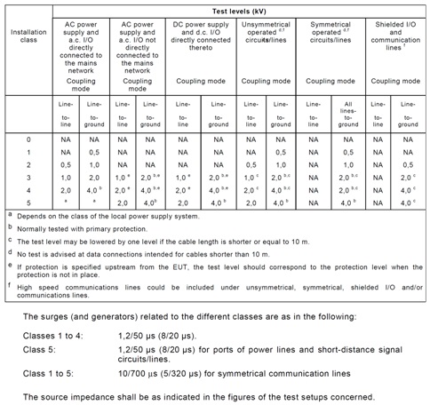
Fig. 8: Table A.1 from the second edition
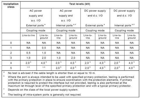
Fig. 9: Table B.1 from the third edition
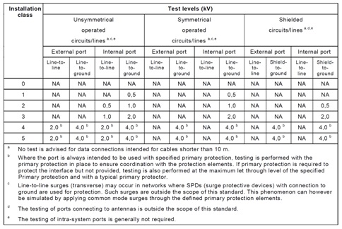
Fig. 10: Table B.2 from the third edition
In addition to the internal/external distinction, note that there are other changes as well: testing of Installation Class 3 DC systems is no longer required. Also, compare the following text (Figure 11) from Annex B of the third edition to the text below Table A.1 of the second edition (Figure 8 in this article): The selection of the proper impulse waveform is made much clearer.

Fig. 11: impulse waveform selection from Annex B (third edition)
Annex C in the third edition (Annex B in the second) is essentially unchanged except for one important clarification: DC power ports, such as ports for providing power to a laptop do not need to be tested.
The new Annex H concerns impulse testing of equipment and power lines rated above 200 Amps. This is probably not something that most readers of this article will need to deal with. Since the impedance of such circuits is so low, any energy from an impulse test is likely to be absorbed. This consideration is reflected in Annex H as well.
Summary
In summary, the changes in the third edition of IEC 61000-4-5 are likely to impact any organization that performs impulse testing or calibrates impulse test equipment. Manufacturers of products that are tested to the second edition will most likely not require any product redesign, as the actual impulse tests are relatively unchanged. The third edition should result in a more consistent application of impulse testing, and greater repeatability of test results.
One final comment: both the old and new versions of IEC 61000-4-5 include the following statement: ” Equipment shall not become dangerous or unsafe as a result of the application of the tests…” (see end of Section 10/9 of edition 2/3 respectively). While the statement seems virtuous and straightforward, it complicates matters significantly if it is strictly interpreted. The IEC 61000 standards do not define “dangerous or unsafe”, not do they list any requirements or tests that can be used to determine if the EUT is dangerous as a result of the applied impulse tests. In product safety standards, a product is considered unsafe if it fails dielectric withstand testing, or if there is excessive leakage current. Both of these situations could occur as a result of a component breakdown during impulse testing (clamping of an MOV or GDT for example). The equipment could remain operational, and otherwise have no indication that it is unsafe. Does this mean that EMC test labs are now obliged to perform electrical safety tests after the completion of impulse testing? Hopefully this is not the case.
[1] C. F. M. Carobbi and A. Bonci, Elementary and Ideal Equivalent Circuit Model of the 1.2/50 – 8/20 μs Combination Wave Generator, IEEE Electromagnetic Compatibility Magazine, Volume 2, Quarter 4, 2013.


