OVERVIEW
This App-Note provides a thorough examination of rectangular and double-ridge waveguides, highlighting their design, operating principles, advantages, and applications. It details specifications and power-handling considerations essential for RF systems.
Waveguides are crucial in microwave engineering, offering low-loss, high-efficiency transmission for communications, radar, EMC/EMI, and scientific applications.
Key topics such as cutoff frequencies, material choices, and power management are explored to offer a comprehensive overview of rectangular and double-ridge waveguides.
Rectangular Waveguides:
Rectangular waveguides are structures used for transmitting electromagnetic waves, particularly at microwave frequencies. They guide waves in a specific direction, often for purposes such as communications, radar, or other high-frequency applications.
Dimensions and Design:
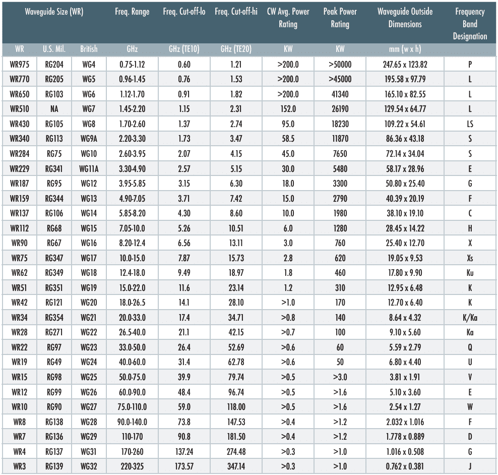
• Dimensions: The dimensions of rectangular waveguides are critical and are typically denoted by the “WR” number, indicating the waveguide’s width in inches. For instance, a WR90 waveguide has an inner width of 0.90 inches.
• Materials: Waveguides are commonly made of aluminum, brass, copper, or other metals with low resistivity.
Poor conductivity metals can also be used if the interior walls are plated, often with silver, to optimize performance and minimize insertion loss.
Millimeter waveguides for frequencies >18 GHz are typically silver-plated to ensure minimal loss.
Operating Principle:
• Mode of Operation: Rectangular waveguides support various propagation modes, with the dominant mode being TE10 (Transverse Electric). This mode has the lowest cutoff frequency.
• Cutoff Frequency: Each waveguide has a cutoff frequency below which signal transmission becomes inefficient, determined by the waveguide’s dimensions.
Advantages:
• Low Loss: Rectangular waveguides exhibit low signal loss compared to other transmission methods, making them efficient for long distances.
• High Power Handling: They can handle high power levels, ideal for various applications.
Applications:
• Communication Systems: Used in microwave systems like satellite communications, terrestrial microwave links, and EMC/EMI testing.
• Radar Systems: Integral components for transmitting and receiving high-frequency signals.
• Scientific Instruments: Applied in instruments requiring precise microwave frequency transmission.
In summary, rectangular waveguides are essential components in the field of microwave engineering, providing efficient and reliable transmission of high-frequency signals.
STANDARD RECTANGULAR WAVEGUIDE

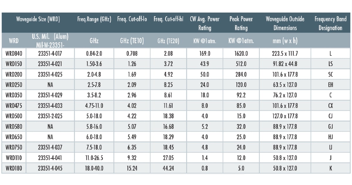
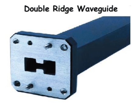
Double-Ridge Waveguides:
A double-ridge waveguide provides a wider operational bandwidth compared to standard waveguide at the cost of higher insertion loss and lower power handling. The “D” in WRD stands for double-ridge.
It features two ridges that protrude into the center of the waveguide, parallel to the short wall. These ridges help to increase the electric field (E-field) within the waveguide, enhancing its performance.
Key Characteristics:
• Increased Bandwidth: The double-ridge design supports a wider frequency range, ideal for applications requiring broad bandwidth.
• Lower Cutoff Frequency: Compared to a standard rectangular waveguide of the same outer dimensions, the double-ridge waveguide has a lower cutoff frequency for its fundamental mode.
• Compact Design: The double-ridge waveguide can achieve compact designs while maintaining high performance.
Enjoying this article?
Subscribe to Interference Technology for expert coverage of EMI, EMC, and signal integrity challenges—plus immediate access to new digital magazine issues.
Subscribe here →
Applications:
• Microwave Communications: Used in systems where wide bandwidth and low loss are essential.
• Radar Systems: Suitable for high-frequency radar applications.
• Scientific Instruments: Employed in various scientific and research equipment requiring precise microwave transmission.
• EMC Testing Applications: Electromagnetic Compatibility (EMC) testing ensures that electronic devices operate without causing or being affected by unwanted electromagnetic interference (EMI).

Power Handling:
Power handling in RF systems is indeed a complex but crucial topic. It’s all about ensuring that components can withstand the power they encounter without being damaged.
Let us break down some key points!
Two Main Limitations:
1. Average Power
Heating Effects: When hardware is subjected to high average power, it can overheat, leading to damage. Effective heat-sinks help mitigate this by transferring heat away from the components.
2. Peak Power
Breakdown Effects (Arcing): High peak power can cause electrical breakdown or arcing. This is where the voltage exceeds the air’s ionization threshold, causing a spark.
Factors to Consider:
1. Average Power
Heat Management: The combined heat from RF and DC power must be dissipated effectively. The quality of heat sinks plays a significant role here.
2. Peak Power
Voltage Limits: It’s crucial to manage the maximum voltage from RF and DC power to prevent breakdowns. The breakdown voltage, about 3,000,000 volts/meter at sea level, is influenced by altitude and gap size but not frequency.
Complex Analysis:
Component Qualification: Ensuring connectors, cables, couplers, antennas, and other components are properly sized for high-power transmission lines is essential. This involves rigorous analysis to prevent failures.
Summary Statement:
This document provides an in-depth overview of rectangular and double-ridge waveguides, emphasizing their design, operating principles, advantages, and applications.
It also includes detailed tables of standard and double-ridge waveguide specifications and power-handling considerations for RF systems.
The content highlights the critical role waveguides play in microwave engineering, offering low-loss, high-efficiency transmission for communications, radar, EMC/EMI and scientific applications.
Key aspects like cutoff frequencies, material choices, and power management ensure reliable and effective operation across various frequency bands.
Understanding these limitations and factors, you can better protect your expensive equipment and ensure efficient and safe operation of your RF systems.