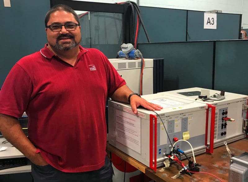
In this special guest-installment for the series of blogs on UNECE Regulation 10, Revision 5, Amendment 1 (8 October 2016), written by Elite Electronic Engineering’s Automotive Test Group Team Leader Stan Dolecki, we will look at electronic sub-assemblies with immunity-related functionality.
Electronic sub-assemblies (ESA) utilized in the European Union require conformity assessment in accordance with UNECE Regulation 10 if the device has an immunity-related function. The objective of testing is to assure the ESA operates reliably to support the safe operation of the vehicle. To confirm operations, a key set of Reg 10 tests are the ISO 7637 vehicle environment transients. In this article, we will review a few key aspects of vehicle transient tests and in particular those ISO 7637 tests for UNECE Regulation 10.
Stan heads up a team of 20 EMC engineers focused on Elite’s automotive electronics testing. At the heart of automotive electronics testing are the applied voltage and current transients characterized in the ISO 7637 and ISO 16750-2 series of standards. The ISO 7637 standards are:
| ISO 7637-1 | Part 1:Definitions and general considerations |
| ISO 7637-2 | Part 2: Electrical transient conduction along supply lines only |
| ISO 7637-3 | Part 3: Electrical transient transmission by capacitive and inductive coupling via lines other than supply lines |
ISO 7637 transients have been readily adopted throughout the automotive industry. They can be found in nearly every OEM automotive and commercial truck specification. They’re also part of construction, agricultural, and mobile machinery specs having 12VDC or 24VDC supply voltage. The ISO standards describe five pulses 1, 2a, 2b, 3a, and 3b.
| Pulse 1 | Simulated transients due to supply disconnection from inductive loads connected directly in parallel with the test item. |
| Pulse 2a | Simulates transients due to sudden interruption of currents in a device connected in parallel with the DUT due to the inductance of the wiring harness |
| Pulse 2b | Simulates transients from DC motors acting as generators after the ignition is switched off |
| Pulse 3a | Simulates negative polarity transients as a result of the switching processes. |
| Pulse 3b | Simulates positive polarity transients as a result of the switching processes. |
Stan shared his thoughts on testing automotive electronic components for susceptibility to power line transients.
Interference -1) If you monitor a vehicle supply voltage bus, it’s not likely the measured pulses will have the precise shapes described in the ISO 7637 standard. Why use these standard shapes if they’re not identical to the transients seen on the vehicle supply bus?
Stan- 1) Certainly the actual measured electrical conditions on a supply bus will appear to be very complex. A time domain capture of the transient conditions looks to be a randomized composite of all waveforms at varying amplitudes, plus much more. Every vehicle make and model will have a different assembly of electronic modules and loads that contribute to the transient electrical environment. But it’s just not practical to capture the transient conditions for every type of vehicle and under all conditions and create a true representation of the pulses to apply in all instances. By using the standardized ISO transients, electronics manufacturers have a specification they can use to design against. The ISO transients provide the characteristics of the vehicle environment in terms of voltage rise time, decay time, and applied energy. They also specify test amplitudes which provide a reasonable margin above actual conditions. The standardized transients also make it possible for the replication of the test conditions in a controlled and repeatable way so that the same tests are applied at any lab.
Interference -2) What are elements of the module design that can affect test results?
Stan-2) This is at the heart and purpose for why we perform immunity tests. As mentioned previously, the standardized pulse characteristics provide designers a specification to meet for handling voltage amplitude, pulse energy, and pulse rise times. Module designers have to provide transient voltage protection using components like transient voltage suppressors (TVS), diodes, zeners, etc. These elements need to be rated for the applied voltage levels and must be able to switch at speeds that outpace the rise time of the applied pulse. This is a difficult task considering there are opposing design objectives focused on reducing component count and cost.
Interference -3) What are elements of the test setup that can affect test results?
Stan-3) The test setup is pretty straight forward. In order to run the test you need the module, a load box, monitoring equipment, and a cable of a specified length. However, if you suspect there is an issue with the setup then first examine the manner in which the test item, loads, and monitoring equipment are grounded. Cable impedances may affect results so be sure to check cable lengths, connector integrity, and cable ground connections. The monitoring equipment can also be a source of inconsistent results. Monitoring equipment can be damaged if not properly isolated from the applied pulses. When you isolate the monitoring equipment pay attention to how the isolation may affect the path of the applied transient.
Interference -4) What are some of the unique challenges in testing automotive electronics for conducted transient immunity?
Stan-4) Some of the modules we test draw significant 12/24VDC current. For example, we have been testing electronically commutated motor controllers that draw 50 to 60 amps of 24VDC current, sometimes even higher. In order to couple transients onto these power leads our test equipment must be able to provide the required high current. The equipment must be designed with the coupling network rated for the pulse conditions and be able to source module power. We can’t test high current products with entry level transient test equipment. Instead, we have to invest in much larger systems that provide the horsepower we need.
Interference -5) How about other tough automotive transient test requests?
Stan-5) The other challenge we face is that not all clients come to Elite asking for the standardized ISO 7636 test. They may require a slight time or amplitude variation to our standard pulses or have a unique pulse shape altogether. We use test equipment configured with arbitrary waveform generators that provide us the ability to create pulses quickly for these special requests.
Interference -6) Voltage variations and load dump are also common automotive test. What challenges to do you find with the ISO 16750-2 tests?
Stan-6) When we test higher current modules we often have to source additional capacity to the handle inrush current during power on transitions. This is another example of requiring high-end transient generators with the capability to handle unique power supply conditions.
Interference -7) Electric and hybrid vehicles are growing in market share. How do you see transient testing evolve to cover the e-vehicle market?
Stan-7) The transient environment for an all-electric vehicle will be different than a conventional IC electric power bus. For sure there’s not an alternator on electric vehicles so certainly the load dump test needs to be re-tooled to represent more typical e-vehicle characteristics. The ISO 7637 pulses that represent motors and inductive systems pulse generators (Pulses 1, 2a, 2b) along with some of the switched transients (3a and 3b) will be relevant for e-vehicle applications. The IEC transients such as IEC 61000-4-4 and IEC 61000-4-5 for AC mains conditions are becoming necessary tor for the vehicle environment. For the high voltage DC lines we’re going to have to use coupled transients rather than any sort of more common supply power capacitive coupled arrangement.
Interference -8) How does your existing test equipment adapt to some of the specialized transient tests that are specified by Asian OEMs like Toyota or Nissan?
Stan-8) Some Asian OEM transients are indeed unique and we can do quite a bit with existing equipment to tailor transients for special requirements. But there are situations where our purchased equipment can’t produce the pulse we need and it becomes necessary to engineer a transient circuit using power supplies, coupling networks, and R-L-C circuit elements.
Interference -9) Some of the automotive OEM specs require very lengthy conducted immunity tests. What characteristics of the test setup lend themselves well to these long-duration tests.
Stan-9) Well here too, conducted transient immunity tests for automotive electronics are being applied for long durations, for example 24-30 hours of continuous pulses. The challenge here is finding a suitable means to monitor the performance of the test item during the test and to do so in an automated manner. It’s too costly to have a person monitor the performance of the test item continuously.


