In part one of this post, I noted that there are three primary EMC coupling problems that are associated with the green wire safety ground:
1. The green wire conducted noise current modulates the signal and shows up as a differential voltage change across the load.
2. The green wire forms a pick-up loop and acts like a magnetic field antenna.
3. The green wire loop acts as a radiator. If the wire or cable that makes up the loop is a large linear structure it can be modeled as a dipole antenna. But if it is a distinctly loop configuration, the model is different. Generally the only known current is the differential current and the models presented below apply rigorously only for the differential mode. The common mode radiation could be estimated based on the default CM to DM conversion values given in item 1 above but as the loop size increases there would be significant error associated with the estimate.
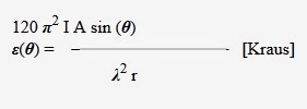
Nevertheless, the simple method Kraus uses to estimate loop radiation makes it easy to understand the issue and provides an approach to solving the radiation problem. For small non-resonant loops, oriented at angle (θ), plane-wave emission levels resulting from loop currents are calculated from:
Assuming the loop is oriented for maximum emission, sin (θ) = 1; converting to frequency instead of wavelength, F (MHz) x λ(m) = 300 m/µs; and introducing the attenuation (as a ratio, not as dB) provided by any shielding, S; the equation can be rewritten as:
Where:
ε(max) = Microvolts/meter
A = Radiating loop area (sq cm), 0.1<(l/w)<10 br="">I = Drive current (amps)
F = Emission frequency (MHz)
r = Separation between the radiating loop and the Measurement point (meters)
S = Shielding effectiveness ratio
A review of the above equation shows that to minimize the radiated emission levels at any given frequency we need to do the following:
1. Keep the loop areas as small as possible
2. Reduce the current
3. Separate the emitter and receptor
4. Add shielding.
I could turn this into a quiz and ask you, “What should I do to solve the interference problem in my office?”, but I won’t. I’ll just tell you.
But first, here’s what I couldn’t do.
1. I couldn’t add shielded cables, because unless the entire CM volume is enclosed, shielding doesn’t work, and I didn’t want to make my office into a shielded enclosure.
2. I couldn’t separate the emitter and receptor any more than I already had without moving the TV out into the yard.
3. I couldn’t reduce the current without modifying the signaling scheme between the computer and the printer. Although I did clamp a lot of ferrite on the power and signal cables and that helped but did not eliminate the problem.
4. The loop area was defined by the location of the printer relative to the computer and I didn’t want to change the layout again.
What I did do was remove the interconnecting cable between the printer and the computer by going wireless. This effectively eliminated the common mode loop. I could have done it by converting to fiber optics at considerable expense and that part stopped me.
I really didn’t want to go to a wireless interconnect scheme because I’m now immersed in a radiated EF environment which-can’t-be-good and the radiated RF energy may contain sensitive personal information . . . like credit card info. I’m not into the conspiracy idiocy but as a TEMPEST design engineer I do have some concern about the hackers. And you should too.
For a good spoof about this whole issue watch: Prime Risk, a pseudo-entertaining film from 1985 about a female EMC/TEMPEST test engineer who discovers a way to rip off ATM machines. She also discovers a group trying to destroy the U.S. monetary system. Some of the stuff is factual some rather hokey.
-Ron Brewer


