A formalized materials qualification process is essential in preventing non-conforming or suspect counterfeit packaging that can lead to ESD hazards during parts inspection process, long-term storage issues and failures in manufacturing.
Robert J. Vermillion, CPP/Fellow, RMV Technology Group, LLC, NASA-Ames Research Park, Moffett Field, CA
The aerospace community has made excellent progress in employing an active defense posture for the inspection of suspect counterfeit parts. From recent industry presentations by the DoD, it does not appear, however, that suspect or non-conforming packaging materials in the supply chain have been considered. Utilization of packaging as a preventative measure in combating the rapid proliferation of counterfeit products will not be addressed in this paper.
The aerospace sector is a relative newcomer to implement anti-counterfeit measures as compared to the medical device and pharmaceutical sectors in the use of packaging engineering countermeasures.
As recently as 2008, the aerospace sector has seen launch delays and issues in space due to non-compliant materials. Since the business model now includes outsourcing with contract manufacturers (CMs) or subcontractors, in-house validation has been replaced by reliance upon the supplier to do the right thing. In addition, reliance upon distribution and supplier driven recommendations is increasing as retirements and layoffs in the aerospace sector continue to accelerate. Consequently, a vendor technical datasheet can prove meaningless unless in-house or third party validation is performed.
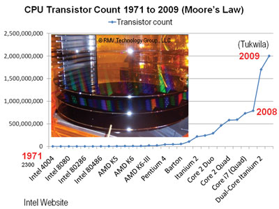
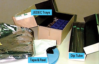
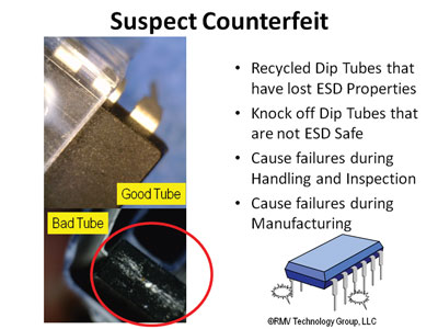
To further compound the matter in today’s business climate, one is more likely to see Class 0 devices (an ESD sensitive device Do current receiving inspection protocols employed by the user and distributor compromise Class 0 ESD sensitive devices during the validation and handling process? Parts 1 and 2 of this article will focus on three major packaging types that are utilized to protect ESD sensitive devices to and from the distributor by the device makers, then received by the customer for in-process manufacturing. To the surprise of the aerospace user and distributor alike, non-compliant or suspect counterfeit antistatic Dip Tube (Rails), JEDEC Trays and Tape & Reel pose real issues. Compliant ESD sensitive devices can be compromised by the use of suspect counterfeit, non-conforming or recycled ESD packaging products.
Electrostatic Discharge (ESD) protective packaging sourcing is not restricted to USA and European sourcing. Products from the Asian Pacific Region provide distributors, CMs and brokers the static control materials and packaging over the web and through new channels of distribution. In recent years, some contract manufacturing (CM) organizations and suppliers may have been sacrificing quality for price. Some issues that were resolved in the early 1990s for ESD packaging are today resulting in corrective actions for ESD protective packaging and material non-conformance.
There are, however, very reputable suppliers of ESD packaging located throughout the world. However, the qualification of a product based upon a supplier’s specification sheet is not enough to insure that company ESD requirements are being met. Organizations need to follow a formalized materials qualification process.
ESD MATERIAL & PACKAGING REQUIREMENTS
For the past several years, many static control packaging schemes have not been in conformance with ANSI/ESD, IEC, MIL-STDs and internal company procedures. Often, the corrective actions stem from so called “knock offs” of brand name products. In addition, requirements for recyclability, Amine free and Restriction of Hazardous Substances Directive (RoHS) requirements by organizations may assist in improving adherence to requirements. The RoHS 2002/95/EC was adopted in February 2003 by the European Union. The RoHS directive took effect on July 1, 2006. Many North and South American, European and Asian organizations have already implemented this initiative. The directive restricts the use of six hazardous materials in the manufacture of various types of electronic and electrical equipment. Each European Union member state will adopt its own enforcement and implementation policies using the directive as a guide. In fact, there could be as many different versions of the restriction as there are states in the EU. RoHS is often referred to as the “lead-free” directive and restricts usage to six substances.[3] A suspect counterfeiter could show adherence in well drafted supportive data, however, real conformance would be in question.
ANTISTATIC TRANSFER
Non-conforming and suspect ESD products can, however, incorporate the use of antistats containing amines. Supplying amine free products can prove costly to the counterfeiter. To dip or spray packaging with a soapy mixture typically found in a grocery store can be utilized as a substitute but with consequences. Issues put to rest in the early 1990s, for example, have resulted in recent launch delays, lessons learned, corrective actions and costly damage of compliant devices during shipping, receiving inspection and manufacturing. Many of these incidents could have been prevented if the materials had been validated for chemical, physical and electrostatic integrity before introduction into the supply chain.
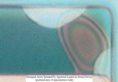
Antistatic transfer of surfactants (amine agents/fatty acids) can cause stress cracking of the polycarbonate structure of a FR4 circuit board. Mirror fogging, reduced soldering capability and discoloration can take place over time. One method of testing is to press an antistatic material (over a given time) against insulative plastic. It has been estimated that an acceleration factor for the MIL-Spec accelerated aging test is approximately 17 days. One day at 1600 F equals 17 days at room temperature.
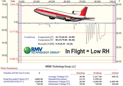
Antistats for long term storage pose issues with longevity and humidity performance during transport and storage. According to John Kolyer, Ph.D. (Boeing, retired), antistats can lose effectiveness at 9% or 10% RH. During transport and shipping, relative humidity will drop during flight and conditions of low RH as seen during winter months in Colorado or Santa Ana Wind conditions in California. Moreover, it is not uncommon to see conditions of <4% RH.
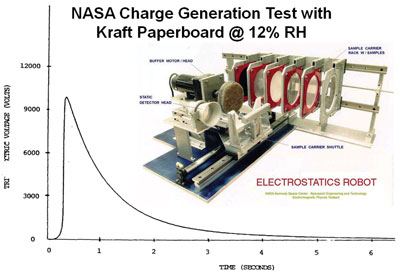
During air transport, RH can drop to 9.33% after 20 minutes in-flight (Figure 4). A 7” x 7” sheet of corrugated Kraft paperboard (cardboard) charged, for example, up to -4403 volts. At 50% RH, the same sheet can charge <10 volts. Dr. Ray Gompf (NASA-Kennedy Space Center, retired) utilized the NASA Tribocharge Generation Test for the evaluation of materials. A small sheet of corrugated (7” x 7”) charged to over +10,000 volts as seen in Figure 5. How does this relate to non-conformance? Moreover, a suspect counterfeit polymer at low RH could charge to many thousands of volts. A suspect counterfeit packaging material would in all probability not be designed for ESD protection.
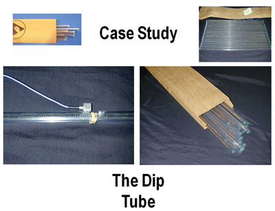
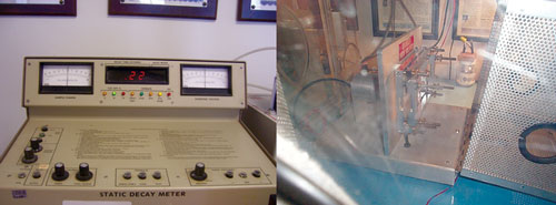
Several component manufacturers have established practices of subjecting dip tubes to physical testing and electrostatic discharge (ESD) testing in order to prevent major associated Field Induced Model (FIM) discharges. Two to four separate tests are utilized for the validation of static control dip tubes as follows:
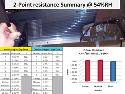
1. 2-Point Resistance for the Inside and Outside per ANSI/ESD STM11.13-2004 (2009)
2. Electrostatic Decay per Mil Std 3010A-2005 (Method 4046)
3. Triboelectric Charge per EIA 541-1988, Appendix B or ESD Adv. 11.2-1994, Appendix A
4. Hand Held Charging per ESD Adv. 11.2, Appendix F
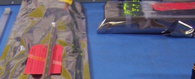
The dip tubes from quarantine as seen in Figure 7 were evaluated for electrostatic decay and charge generation.
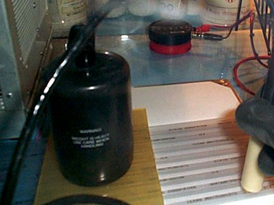
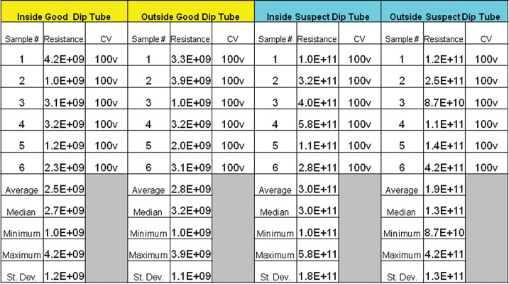
In this case, the Dip Tubes were cut into 12” lengths for testing at 12% +/- 3%RH, 730F +/- 50F after 48 hours of preconditioning (Figure 8). The NFPA 5-lb weight atop the insulative Plexiglas prevents movement in the chamber and isolates each tube for resistance testing. Not pictured is the measurement inside the dip tubes after circular sawing in half. Passing constitutes readings of <1.0 x 10¹¹ ohms.
ELECTROSTATIC DECAY
The 6-inch cut dip tubes were placed into the fixturing of the calibrated ETS 406C testing unit.
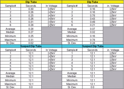
The test requires conducting measurements at +/-5000 volts to 0 volts for an electrostatic decay in <2.0 seconds. Tables 2a and 2b illustrate the results. The compliant dip tube as highlighted in yellow produced decay times of <2.0 seconds. However, the insulative non-compliant dip tube decay was over 2.0 seconds. The test was called at 12.1 seconds as the decay time continued to run for several minutes.
FARADAY CUP (Q=CV)
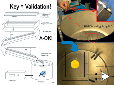
After the dip tubes are ionized to remove stored charge, a grounded operator begins testing begins by lifting the dip tube and teeter tottering the rail at 450 allowing the compliant components to free fall into the Faraday Cup as seen in Figure 10. Some organizations require a passing score of <+/-1.0 nC or about <+/-100 volts. Table 3 illustrates the results of testing between the compliant dip tubes and non-compliant antistatic plastic rails that housed compliant ESD sensitive devices.
FIELD EVALUATIONS FOR STATIC CONTROL COMPLIANCE
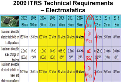
It was not surprising that a non-compliant dip tube would fail initial testing. However, during in-house assessments in the semiconductor and aerospace sectors with end users, contract manufacturers (CMs) and component distributors, non-compliant and suspect counterfeit dip tubes are utilized to package ESD sensitive devices. ESD components in an aerospace environment may be sensitive to <50 volts (Figure 4). Are receiving inspection end users and distributors putting Class 0 ESD sensitive devices (<250 volts limit) at risk?
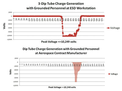
What happens to a dip tube at 50%RH on a grounded ANSI/ESD S4.1-2006 compliant workstation? Three non-compliant dip tube specimens were held under ionization for 10 seconds to remove charge while grounded. Dip tubes were then placed on the ESD safe workstation at the RMV NASA-Ames lab. Said tubes were pulled a distance of 6 inches across the workstation and lifted up to a computer interfaced non-contact voltage probe. The bottom graph in Table 5 illustrates measurements taken at an aerospace CM with a non-compliant dip tube containing validated ESD sensitive components.
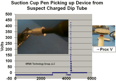
The CM results in Table 5 generated a corrective action for the dip tube supplier. Table 6 illustrates what could happen when a distributor (with quarantined dip tubes) handles ESD components during the inspection process. ANSI/ESD S20.20 and several organizations require maximum voltage to be <+/-100 volts at the ESD safe workstation. However, handing Class 0 devices during the receiving inspection process with ESD sensitive components at <50 volts could be compromised with suspect dip tubes. For example, a dip tube was picked up and handled by a grounded distributor (Table 6) while removing ESD sensitive components from the dip tube rail with a suction cup vacuum wand to rest atop a proximity voltage antenna (Prox V).
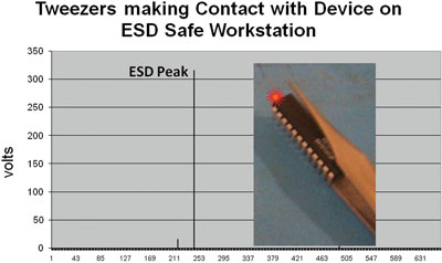
Table 7 illustrates metal to metal contact (Machine Model) between the stainless steel tweezers and component leads that make intimate contact with an ESD sensitive device as it exits a suspect or non-compliant dip tube. As the tube was charged, the path of least resistance is from the leads of the device to tweezers and ground. Consequently, a peak discharge of over 300 volts was recorded by the ESD event antenna a foot away.
IN-PROCESS MANUFACTURING
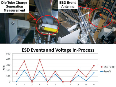
Said customer had failure issues during manufacturing with ESD sensitive devices. The machine center was process assessed (troubleshooting) for ground integrity and resistance to ground at pre-selected critical spots. However, after placing a non-contact voltage probe and ESD Event antenna during manufacturing (Table 8), corresponding electrostatic discharges took place during manufacturing costing thousands of dollars. The resistance and charge generation of the dip tubes were high.
The suspect dip tubes were identified as being recycled and rewashed. IPA or de-ionized rinsing can strip topically coated antistats from PET-G or APET polymers. Table 9 illustrates the results of suspect tubes when using the 2-point resistance testing.
In summary, despite ESD symbols or markings, static control packaging requires validation in addition to reviewing a vendor’s technical data sheet. After testing dip tubes in the lab and field, non-compliant dip tubes can fall into three categories: suspect counterfeit, non-compliant or recycled. The aerospace quality assurance effort during the inspection of suspect counterfeit components needs to include physical testing of dip tubes to insure that the receiving and outgoing inspection process is not compromised by insulative or contaminated dip tubes. A follow-up of this paper will address suspect JEDEC trays and Tape & Reel issues related to non-compliance and suspect counterfeiting.
REFERENCES
[1] Non-compliant or Suspect Counterfeit Materials Can Lead to ESD Hazards and Long-Term Storage Issues, Bob Vermillion, NASA QLF, Kennedy Space Center, 18 March 2010
[2] Electronic Part Damage by Antistat Vapor, John Kolyer, Ph.D., Arie Passchier, Ph.D. and WG Peterson, The Boeing Company
[3] Wikipedia
[4] ESD from A to Z, Dr. John Kolyer and Watson, 2nd Edition
[5] Mil Handbook 1686C-1995
[6] Mil Handbook 263B-1994
[7] EIA STANDARD
[8] Packaging Materials Standards for ESD Sensitive Items, EIA-541, June 24, 1988, Appendix C, “Triboelectric Charge Testing of Intimate Packaging Materials”
[9] ANSI/ESD S20.20-2007
[10] ANSI/ESD STM4.1-1997
[11] ANSI/ESD STM11.13-2004
[12] ESDA Adv. 11.2-1995
[13] Using An ESD Packaging Materials Qualification Matrix for Contract Manufacturing and Supplier Conformance, Sep 1, 2006, Albert Escusa, Texas Instruments and Bob Vermillion, RMV Technology Group, LLC
[14] Ed Dimmler, PCX Inc. for Specimens
[15] Dr. John M. Kolyer, Ph.D., Rockwell International, Telephone interview in 2004
[16] The Charged Device Model & Work Surface Selection, John Kolyer and Donald Watson, October 1991, pp. 110-117
[17] Humidity & Temperature Effects on Surface Resistivity, John Kolyer and Ronald Rushworth, Evaluation Engineering, October 1990, pp. 106-110
[18] Military Handbook-263B-1994
[19] Triboelectric Testing at KSC Under Low Pressure and Temperature ESD Association Proceedings 2002, Dr. Ray Gompf, PE
[20] ITRS Technical Requirements – Electrostatics, The ITRS is devised and intended for technology assessment only and is without regard to any commercial considerations pertaining to individual products or equipment
[21] Intel Website, Moore’s Law
Bob Vermillion, CPP/Fellow, is a Certified ESD & Product Safety Engineer-iNARTE with practical and “hands-on” expertise in the mitigation of material Triboelectrification on a Mars surface and in troubleshooting robotics or systems in aerospace, disk drive, medical device and pharmaceutical, automotive and semiconductor sectors. A co-author of several ANSI level ESD documents, Bob serves on the BoD with iNARTE, is a member of the ESD Association Standards Committee and conducts ESD Seminars in the USA and abroad, including guest speaker engagements for California State Polytechnic University, San Jose State University, University of California at Berkeley and Clemson University. In June 2010, Bob will conduct a seminar at Oxford University. Bob is Chief Technology Officer of RMV Technology Group, LLC, a 3rd Party ESD Materials Testing and Consulting Company. He can be reached at 650-964-4792 or bob@esdrmv.com.
