
Due to the rapid densification of ESD sensitive devices (ESDS), static control resilient flooring (ESD flooring) has found its way into FAA towers, operating room theatres, MRI/CT scan flooring areas, aircraft terminals, IT data centers, Navy ships, space & defense flight lines, call centers, medical device manufacturing, pharmaceutical delivery and the manufacturing/assembly of microprocessor driven devices.
In 1971, Intel’s 4004 microprocessor equaled about 2300 transistors as compared to today’s new vertical field-effect transistor (VFET) manufacturing process that built microprocessors with the world’s most powerful chip, the Apple M1 Ultra at 114 billion transistor equivalencies.
An individual walking on an insulative tile floor can build up static electricity resulting in electrostatic discharges (ESD). When a hand touches a doorknob, it can take 3000 to 3500 volts to feel a sudden shock. Modern day microprocessors used in space & defense, cell phone and touch display pads can be killed at ±35 volts or below.
Static control flooring is manufactured for form and fit as follows:
- Raised Data Center Flooring
- Polymer Cushioned Floor Mats
- Tile
- Laminated Steel Framed Flooring
- Concrete
- Coated Floor Tile
- Modular interlocking or Snap-In Flooring
- Polymer Lay Down Floor Sections
- Special ESD Composite Flooring
- Special Antistatic Coatings
- Epoxy
- Interlocking Tile Flooring
- Carpet
Both non-compliant and suspect counterfeit static control flooring have infiltrated the supply chain. Today, a common practice by federal agencies is to require third-party installation certification of a static control floor before payment is issued. In order to prevent the potential bias of supplier self-certified testing, third-party qualification or installation certification ensures independent verification.
For proper selection and installation of static control flooring, several ESD flooring standards are being utilized. U.S. Government agencies call out a 09 6X XX designation for static resilient flooring. For instance, the DOT & FAA utilize 09 65 36. The federal sector references ASTM F150 and ANSI/ESD STM7.1 resistance testing for static control flooring protocols. So that everyone is on the same page, the definition of floor resistance is:
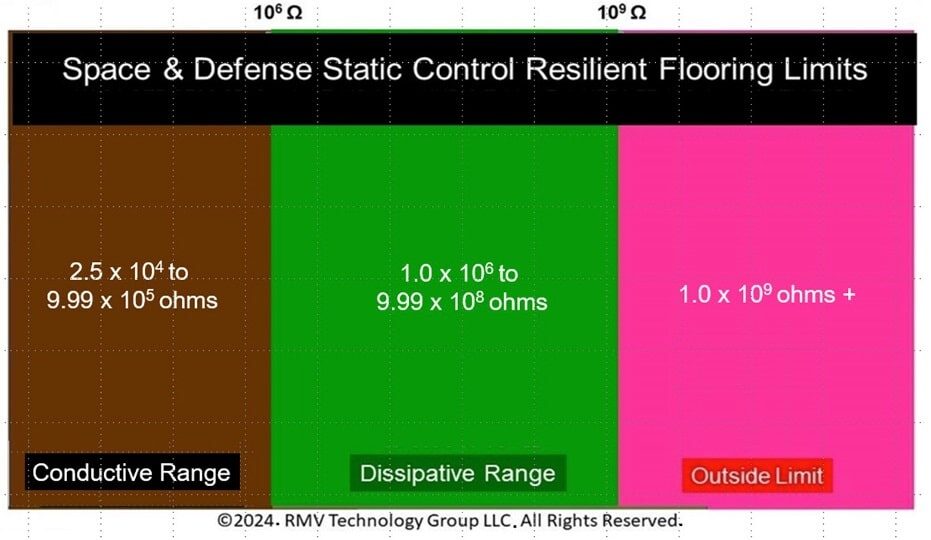
ASTM F150 Conductive flooring material: A floor material has a resistance between 2.5 x 10⁴ ohms through 1.0 x 10⁶ ohms. Dissipative floor material: A floor material has a resistance between 1.0 x 10⁶ ohms to 1.0 x 10⁹ ohms.
ANSI/ESD STM7.1 Conductive flooring material: A floor material has a resistance of less than 1.0 x 10⁶ ohms. Dissipative flooring material: A floor material has a resistance of greater than or equal to 1.0 x 10⁶ ohms and less than 1.0 x 10⁹ ohms.
Important Notice regarding Constant Voltage (CV) for Resistance: Since the DOD has adopted ANSI/ESD S20.20, Resistance to a Groundable Point (RTG) and Point to Point (RPP) resistance shall be between 2.5 x 10⁴ ohms to <1.0 x 10⁶ ohms for conductive flooring with a CV of 10 volts, for a RTG and Rpp between 1.0 x 10⁶ ohms to < 1.0 x 10⁹ ohms, static dissipative flooring requires using CV=100 volts.
The Space & Defense sector has set a lower floor resistance of 2.5 x 10⁴ ohms for personnel safety purposes as illustrated in Figure 2.
A new installation shall have no individual reading greater than the stated limits defined in Electrostatic Discharge (ESD) ANSI/ESD STM7.1 or ASTM F150. In addition, the plant or civil engineer, architect, facilities engineer, general contractor and ESD Program Manager should consider the following testing methods.
- ANSI/ESD STM7.1 Resistance to a Groundable Point (RTG) at <1.0 x 10⁹ ohms.
- ANSI/ESD STM7.1 Point to Point Resistance (RTT) at <1.0 x 10⁹ ohms.
- ANSI/ESD STM97.1 Resistance in Combination with a Person at <1.0 x 10⁹ ohms.
- ANSI/ESD STM97.2 Voltage in Combination with a Person at <±100 volts.
- Electrostatic Decay to satisfy US Government 09 6X XX designation requires Mil-STD-3010C, Method 4046 at ±5kV to 0 V in <0.25 seconds.
- Verification of static control footwear using ANSI/ESD STM9.1.
One way to ensure a greater understanding of the requirements for ESD qualification is to show segments of SelecTile Conductive Black testing taking place in RMV’s lab at NASA Ames.
1. ANSI/ESD STM7.1
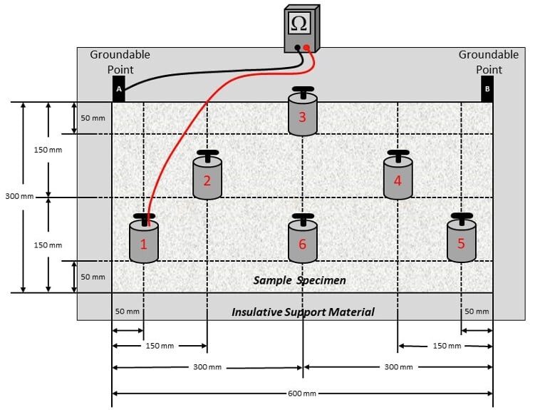
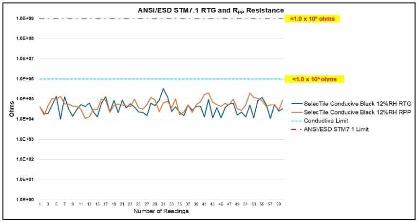
In conducting ANSI/ESD STM7.1 qualification testing for RTG and RPP resistance, a test pattern is called out as illustrated in Figure 3.
The five (5) test specimens shall be large enough that a 305 mm (12 inches) by 610 mm (24 inches) where a test area can be defined. Evaluation takes place in a preconditioned environment at both 12 ± 3% relative humidity (RH) and 23oC ± 3oC or 50 ± 5% relative humidity and 23oC ± 3oC (73oF ± 5oF).
Preconditioning of the specimens shall be a period of at least 72 hours. Note: some flooring materials (carpet) may require longer time to reach the desired level.
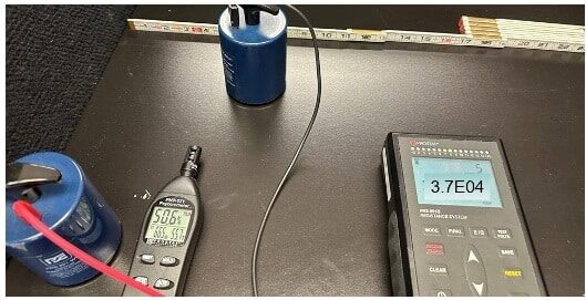
Resistance measurements are first conducted by connecting one lead to a Groundable Point A (GP-A) and placing the NFPA 5-lb electrode at six positions (1 – 6) clockwise from bottom left to left to right for RTG (Figures 3 and 4) and RPP measurements using the appropriate CV of 10 volts for conductive flooring.
After the first six measurements are taken, the lead is connected to GP-B and the measurement takes place in a counterclockwise manner from bottom right to left.
The initial RTG and RPP readings fell within the acceptance range for ESD control compliance at 50%RH after 72 hours of preconditioning. Every specimen measured at <1.0 x 10⁶ ohms for a “conductive” designation. At 50%RH, the floor’s performance should be less susceptible to charging.
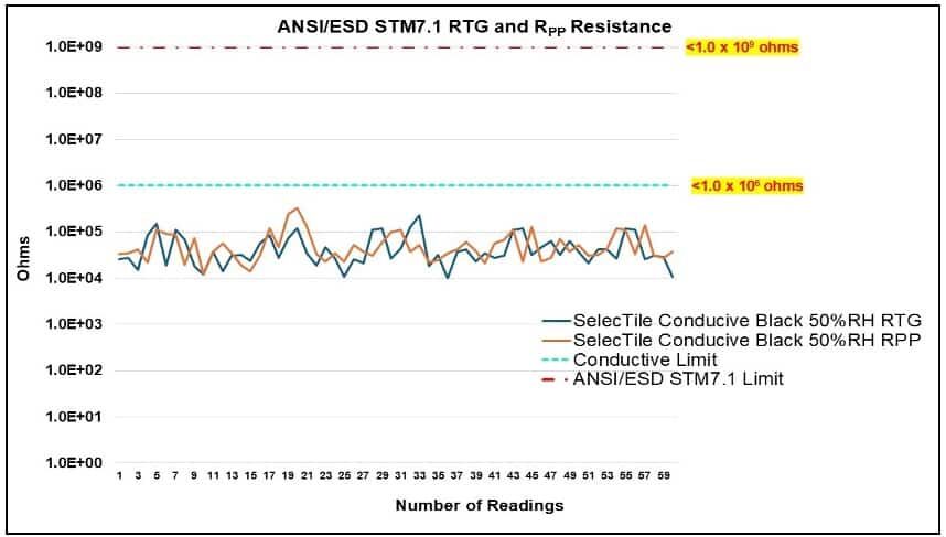

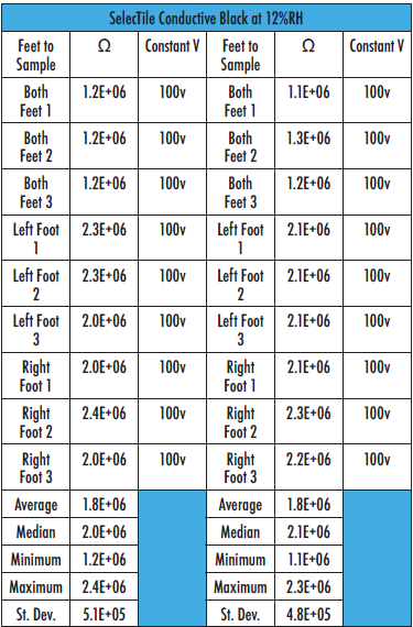
The completed set of data tables (due to size restrictions) were not listed in this article. Table 1 represents the format used in this report. Data tables are posted online; the resistance summary illustrations, however, can be viewed in Figures 5 and 6.

Testing at 12±3%RH determines if the flooring maintains its resistance integrity in areas that could be subjected to winter or Santa Anna Wind conditions when the humidity could drop to 4% to 7%RH.
Results for the conductive flooring were favorable at 12%RH, producing results within 2 orders of magnitude.
Two NFPA 5-lb electrodes were verified before conducting measurements at 1.1 x 10² ohms.
2. ANSI/ESD STM97.1
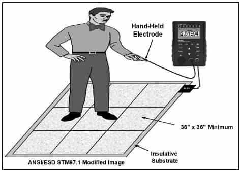
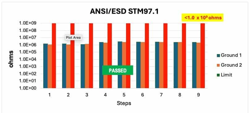
ANSI/ESD STM97.1 measures the electrical system resistance of floor materials in combination with a person wearing static control footwear. ANSI/ESD S20.20 sets a limit of <1.0 x 10⁹ ohms.
This test is useful to determine the resistance of a floor and a person wearing static control footwear such as shoes, heel and sole grounders. The resistance of the footwear influences the readings despite the floor’s individual resistance measurements measured slightly above 1.0 x 10⁶ ohms.
As a system, a person wearing ESD footwear has greater contact area combined with a higher resistance compared to NFPA 5-lb electrodes.
Stay tuned for Part 2 of this article, which will discuss ANSI/ESD STM97.2, ANSI/ESD STM97.2 walking tests, and electrostatic decay.
Acknowledgement:
A Special Thank you to Mr. Thomas Ricciardelli, CEO & Owner of SelecTech, Inc., Flooring Products for providing the samples for testing that made this article possible. Tom can be reached at 508.583.3200 or tricca@selectech.com


