Mart Coenen
EMCMCC, Breda, the Netherlands.
Most, if not all electrical and electronic appliances have to be tested on their radiated RF emission and their immunity against RF radiated fields. This radiated testing occurs either on an open area test site (OATS) or in an anechoic or semi-anechoic room (SAR). The electrical and electronic appliance to be measured will be put on a turntable with a 0,8 to 1,0 m high table (table-top equipment) or floor (floor-standing equipment). Cables to be connected to operate the appliance as intended are an everlasting point of discussion w.r.t. their functional and common-mode termination against the metal reference plane/floor of the OATS or SAR, in particular for the mains lead connection.
In the different EMC norms and standards, the RF emission requirements are set w.r.t. the maximum field strength, mostly defined by E-field values, to be measured or the equivalent radiated power (ERP). These measurements then need to be carried out at 3, 10 or 30 meter distance from the appliance to be tested. These measurement sites all need to comply with the normalized site-attenuation (NSA) by using normalized antenna factors, this to ensure that the radiation measurements as taken at one place agree, with tight tolerances to the results taken from another test site. To determine the test site’s NSA, 2 or 3 (free-field) calibrated antennas shall be used.
The appliance, floor-standing or table-top, to be tested on its radiated RF emission has to be placed at the location where the transmission antenna was set before i.e. above the center of the turntable, while the receiving antenna stays in place. The appliance then needs to be connected with all cables to be able to it operate as intended. However, the appliance with all cables connected behaves as a non-predicable undefined antenna topology of which the cable orientation and their functional and common-mode termination determine the antenna efficiency as function of frequency.
While measuring on an OATS or in a SAR with a metal ground plane on the floor, all cables connected to the appliance will be connected to it or routed on it. The cable lengths, their routing and their termination determine the resulting cable current distributions which determine the antenna efficiency i.e. the radiated power as function of frequency from the appliance as a whole. Optimal impedance mismatch is nice to achieve easy compliance. Trying to achieve the worst-case RF emission by altering the cable topology: routing and length, as function of frequency is near to impossible to do.
For the connection of the mains cables, the Artificial Mains Network (AMN, IEC CISPR-16-1-2) is prescribed, see IEC CISPR 11 and 32, where the AMN has a series impedance of 50 Ω // (50 µH + 5 Ω) for the phase and neutral wires against the metal ground plane being the protective earth (PE) but an impedance of zero (= RF short-circuit) for the PE-wire itself. The impedance definition of the AMN is typically limited to 30 MHz, just where the radiated emission measurement start. An alternative termination network would be a coupling and decoupling network (CDN) or asymmetric artificial network (AAN) which represents in common-mode an impedance of ~150 Ω for all wires to the metal ground plane, typically up to 230 or 300 MHz.
With the construction of EMC measurement facilities, often heavy, multi-section mains filters are used at the control area of an OATS or at the outer wall of the Faraday cage with a SAR, typically far away from the mains wall outlet mounted in or beneath the turntable location i.e. there where the appliance to be connected to and will be located. As most, if not all, mains filters have a -filter (CLC) structure, their output impedances against PE i.e. the metal reference plane at their mounting positions can be seen as an RF short-circuit. As the mains supply distribution at an EMC test facility is not built RF-wise (other than being shielded), the impedances at the far-end, being the wall outlet will be undefined for the phase and neutral wires, this under the assumption that the PE-wire of the wall outlet is directly connected to the metal plane of the turntable (which is not true in many cases either). In either case, the common-mode as well as the asymmetric mode impedances at the wall outlet are undefined. The use of an additional AMN or CDN with such an impedance undefined mains outlet then seems the only way out.
If the appliance is provided with multiple ports, screened or non-screened, it will be common that the outer screens of the shielded cables are directly connected to the metal reference plane of the turntable underneath the appliance under test. With non-shielded signal and supply lines all options are open again, from infinite impedance e.g. using a battery operated load or source or an electrical-to-optical interface towards the control area. The common-mode impedance will be undefined and vary between an open-end to an RF short-circuit. Simple examples are: nautical equipment, being insulated from the ship’s body or hard grounding as it occurs in a combustion engine environment of a vehicle. These options deliver the 2 or 3 extremes with RF emission measurements: a node, an anti-node or an ideally damped/ terminated condition at the far-end of a cable, leading to varying test results with over +/- 20 dB per frequency when that cable termination is dominant for the total RF emission performance.
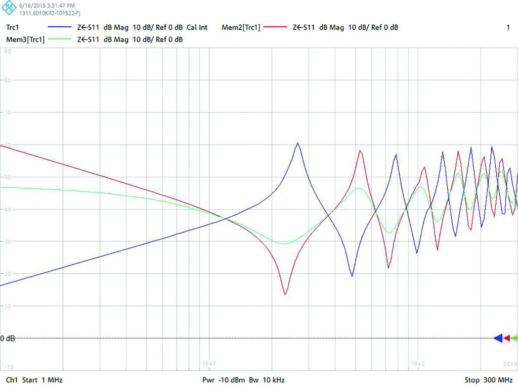
Figure 1 – Asymmetric impedance measured following a 1,5 meter long mains lead with open, short-circuit and 50 Ω termination at the near-end of the cable 3 x 0,75 mm2
Figure 1 shows the asymmetrical (neutral/ phase) impedance, in dBΩ, as function of frequency, in the range 1 to 300 MHz, when a 1,5 meter long mains lead is used. Here the near-end is left open, short-circuited or terminated with 50 Ω against the reference, which is again hard grounded to the metal reference plane.
The frequency scale runs logarithmically from 1 to 300 MHz and the absolute impedance is running from -10 dBΩ (= 0,3 Ω) to 90 dBΩ (= 30 kΩ). The RF radiated emission measurements start (according standards) from 30 MHz, there where impedance-resonances for a 1,5 meter long mains lead start. If there is hidden mains cable length at the test facility, in-between the wall outlet and the OATS or SAR mains entry filter of the test facility, impedance resonances will already start at much lower frequencies.
Inconsistency in norms and standard
The various EMC norms and standards sometimes require an AMN, a CDN or a MDS, EM or ferrite clamp and sometimes nothing w.r.t. the impedance definition at the mains wall outlet or mains lead with a radiated RF emission or RF immunity test. As indicated, this could lead to 40 dB of difference in test results at a specific frequency. This won’t show with up with an envelope of a broadband interference source, as there always will be one or many spectral lines which coincide with the maximum antenna efficiency of the cables connected, in particular the mains cable.
Unfortunately in the last version of IEC CISPR 32 reference is made to an AMN i.s.o. a CDN. In the update proposal of IEC CISPR 11, the two networks are even in series: AMN and CDN. The single use of an AMN results in nodes for the PE-wire and a relative impedance definition for the neutral and phase wires against PE, though as earlier indicated just defined up to 30 MHz. By application of an ideal AMN following an RF impedance undefined wall outlet, the impedance at the AMN between neutral/ phase and PE becomes 34 dBΩ (= 50 Ω) with a close to ideal minimal impedance variation in the frequency range 1 – 300 MHz, see figure 2, which then still results in impedance variations at the appliance following a mains lead of 1,5 meter equal to figure 1, 50 Ω case.
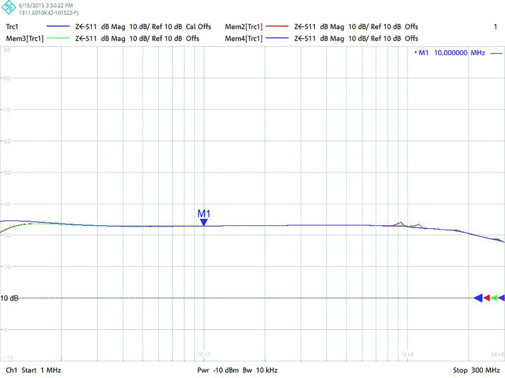
Figure2 – Asymmetric impedance at the EUT side of an AMN with open, short-circuit and 50 Ω at the supply side.
Figure 2, shows, in contradiction with the requirements of IEC CISPR 16-1-2 that a compact dummy AMN can be made, see figure 3, by which a fair impedance of 50 Ω can be realized till far above 30 MHz. This is something which cannot be achieved by commercially of the shelf (COTS) AMNs.
One remaining constraint is that the wall outlet to which the dummy AMN is applied has its PE terminal directly connected to the metal reference plane of the turntable. An alternative will be to have an additional PE terminal on the dummy AMN which shall make contact to the metal reference plane of the turntable.
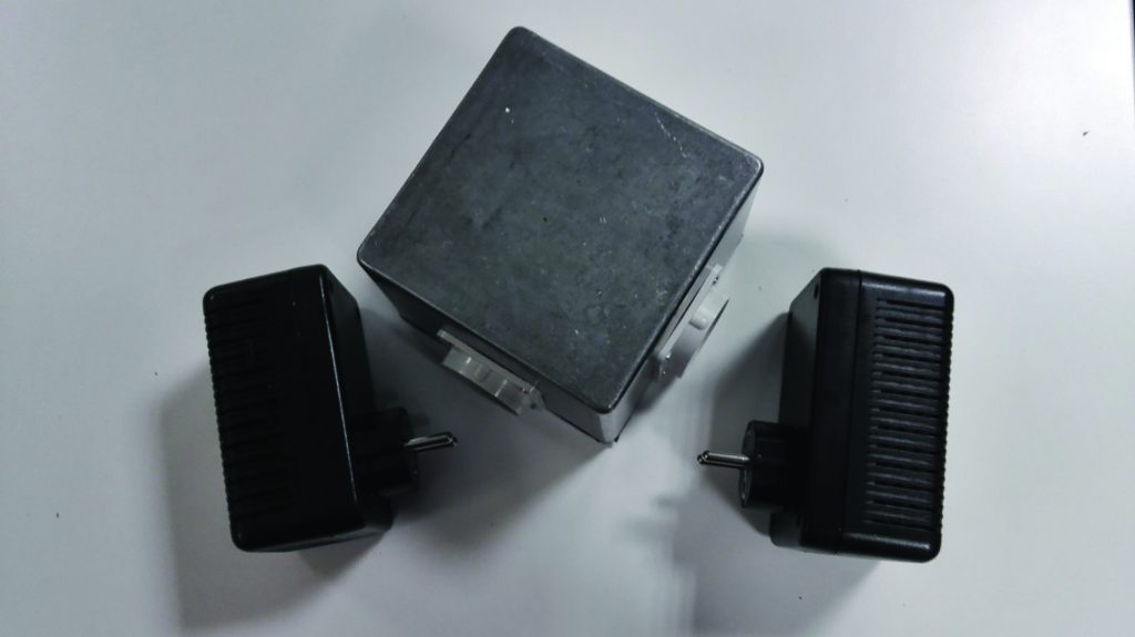
Figure 3 – Photo of a dummy AMN and dummy CDN together with a calibration network with an open, short-circuited and 50 Ω terminated wall outlet box.
Another approach which has attempted in the several revisions of IEC CISPR 22 is to define a ferrite clamp e.g. the MDS-clamp on the mains cable as well as other cables to control the common-mode impedance. Common-mode impedance values between 50 and 500 Ω (= 34 – 54 dBΩ) were set as target.
For mains and other 2 and 3-wire unshielded signal and supply lines an appropriate CDN which is terminated with 50 Ω can be used. E.g. a terminated CDN M2 or M3 (conform IEC 61000-4-6) can be used. Also here a dummy CDN can be created which is not intended for measurement purposes but just to represent the 150 Ω (= 44 dBΩ) common-mode impedance to either a 2 or 3 wire mains connection. The network has been realized in the same housing as the dummy AMN, see figure 3. The common-mode impedance shall be similar to the requirements of IEC 61000-4-6, see figure 4. Similar to the dummy AMN, the dummy CDN supply port is terminated by an open, a short-circuit and a 50 Ω termination while the EUT port impedance is observed as function of frequency. The values of the absolute impedance may vary, for frequencies beyond 26 MHz, between 106 and 212 Ω, or 44 dBΩ ± 3 dB = 41 to 47 dBΩ, which is well within the range as defined by IEC CISPR 22 where 34 – 54 dBΩ were given as lower and upper bound.
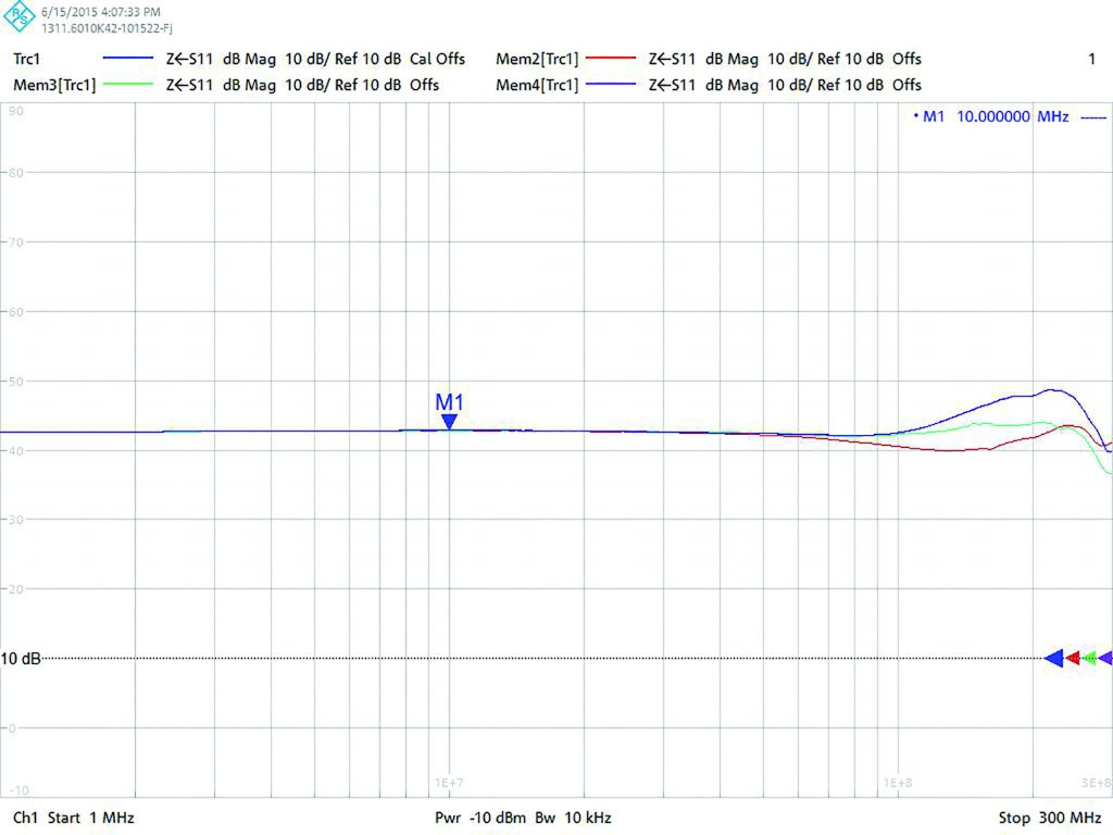
Figure 4 – Common-mode impedance at the EUT side of the dummy CDN where the supply side is left open, short-circuited or terminated by 50 Ω
Without these impedance stabilizing measures with a dummy CDN, the wall outlet impedance could vary between extreme values as given in figure 5, being the output of the wall outlet calibration box but taken the class I mains plug (= with PE) length and its stray capacitance is taken into account. The common-mode impedance is measured following 1,5 meter extension lead and is given in figure 6.
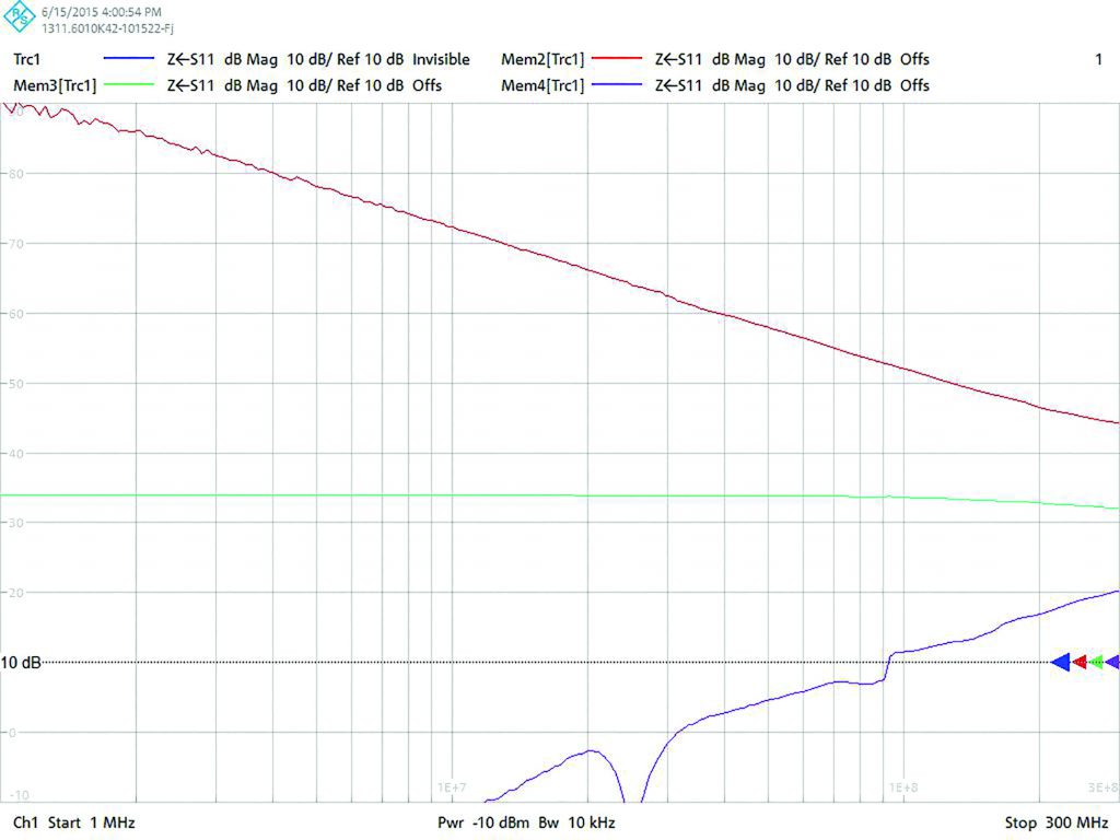
Figure 5 – Common-mode impedance at the end of a 3-terminal mains plug when connected to the open, short-circuited and 50 Ω terminated wall outlet box.
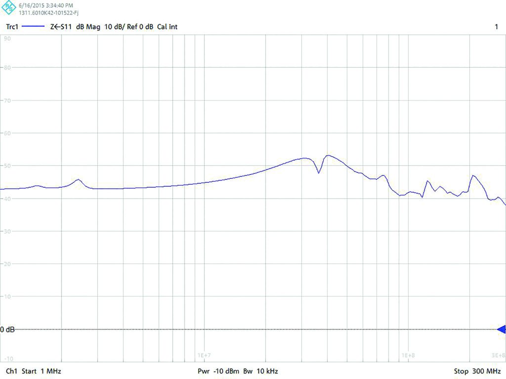
Figure 6 – Common-mode impedance at the EUT side of a CDN after 1,5 meter mains extension lead with open, short-circuit and 50 Ω termination at the supply side
Conclusions
If an electric or electronic appliance fails with a radiated RF emission or RF immunity test one could ask one selves whether the functional and common-mode cable termination applied agree to what one has expected. Even if one passes the tests, one should ask one selves whether these terminations have been correctly applied. Meeting these impedance constraints will enhance measurement reproducibility and minimize the variations with compliance uncertainty in an easy way.
With a great number of EMC test houses and test facilities the impedances behind the mains wall outlets at the OATS or in the SAR at the turntable are fully undefined leading to large variations of the radiated measurement results even though the NSA requirements are met. A similar constraint applies for all other non-shielded signal/ control/ communication and supply lines. This lack of impedance definition also occurs with the wall outlets at compact EMC cages, TEM-cells and mode-stirred chambers (MSC). The lack of impedance definition mainly shows in the frequency range up to 300 MHz. Above 300 MHz the enclosure radiation will typically dominate i.e. become an effective antenna
The various EMC norms and standards are not unambiguous about the way that the impedance termination at the mains cable has to be provide with the radiated tests. As a result, this is done by the ‘own interpretation’ of the test house i.e. engineer who is performing the tests, leading to large deviations in test results, mostly too negative.
By using one or two simple dummy networks: AMN and CDN one can verify the influence of the mains cable termination. A prescribed choice will enhance the reproducibility and inter-laboratory comparison of the test results.
N.B. Applying a dummy AMN and CDN network in series will be useless as only the ‘last’ network connected to the mains cable towards appliance will dictate the termination impedances (as it was the intention of these dummy networks to eliminate whatever impedance there was at the supply side of the network concerned).


