EMC regulation of solar installation equipment has failed to keep pace with actual developments.
Siegfried W. Best
As populations throughout the world become more aware of environmental issues and the necessity of forestalling further damage and pollution, attention has been focused on finding eco-friendly means of generating electric power. Wind farms are one highly touted solution. The other is producing current using the photovoltaic cells found in solar panels.
One critical subsystem of solar, or photovoltaic, installations is the solar inverter. These devices carry out the key step of feeding the newly generated power into the power grid. Like every advance in the use of electricity from incandescent light to the latest sleek laptops, the flow of electrons brings the possibility of errant energy resulting in electromagnetic interference. Of course, the next logical concern is preventing or attenuating this interference and achieving electromagnetic compatibility or EMC. Further, the inherent concept of EMC involves defining certain limits that allow multiple devices and systems to function efficiently without causing problems or suffering impairment caused by interference. Finally, the ultimate achievement of this ideal mandates standards that define the limits and test procedures and specify the test equipment that can assure that true compliance has been achieved.
SOLAR INVERTERS AND EMC: THE DILEMMA
At present, assuring the EMC compliance of solar inverters is problematic. The amount of power generated is considerable, and an abundance of caution is the only prudent course. Another complication arises in dealing with the efficiency ratio—i.e., maximizing the percentage of the power generated by the solar installation that actually makes it into the grid as usable power. A high efficiency ratio means fast switching operations with their inherent steep rise and fall times and interference. Also, the push for designing economical solar inverters has resulted in topologies without transformers. Such designs result in high voltages and fast rising voltage spikes—along with the unintended side effect of EMI.
RELEVANT STANDARDS
Like many other areas of swiftly changing technologies, EMC regulation of solar installation equipment has failed to keep pace with actual developments. At present, there are no specific standards regulating solar inverters. In fact, there is no precise category for these devices. At various times, solar inverters have been defined as household appliances; ISM (industrial, scientific, medical) equipment; or as information technology components. These arbitrary descriptions would make solar inverters subject to EN55014, EN55011, or EN55022. Presently, efforts are underway to create standards applying specially to photovoltaic power generation systems. Committee K 373 of the DKE has divided efforts into five discrete projects, creating standards specifically for: solar cells, solar disks/panels; connectors used in photovoltaic systems; verification of simulation programs of photovoltaic systems; and building construction of photovoltaic systems.
The need for Committee K 373’s efforts could not be more evident. Today, manufacturers of solar inverters claim compliance and affix the CE Mark to their devices by asserting that they meet the requirements of the following standards:
- Appliance safety in accordance with IEC 60950-1:2003-08 as well as EN 50178:1998-04
- Emissions in accordance with 61000-4-6-3:2002-08 as well as EN 61000-6-4:2008, as well as EN 61000-6-4:2002-08
- Power feedback to the mains in accordance with EN 61000-3-2:2001-12

TEST SYSTEM FOR SOLAR INVERTERS
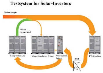
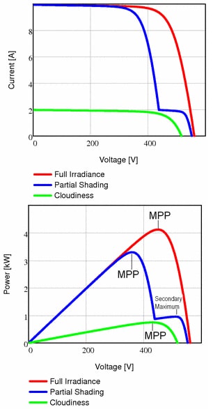
One recent development that promises to clarify the present confusion about the standardization of solar inverters is the availability of a complete test system including a mains simulation unit (with power feedback) and a PV (photovoltaic) simulator unit (Figure 1). The PV simulator mimics the behavior of the solar panels. A system of precise controls allows the user to adjust or readjust the program quickly to simulate the characteristics of different types of solar panels and their varying power outputs. Both stable and turbulent weather conditions can be simulated accurately (Figure 2). This latter feature provides a key parameter for EMC testing—repeated measurement under precisely the same conditions.
The output of the PV simulator is fed into the mains simulation unit, which also includes measurement instrumentation calibrated to check emissions and immunity limits in accordance to the relevant EN standards. A recovery unit allows for a considerable degree of heat dissipation, thus the test system is suitable for solar inverters of a few kW up to and over 100 kW.
THE BASIC EMC SYSTEM
The basic unit for the mains simulation unit is a four-quadrant amplifier, an AC/DC voltage source needed for the field of low-frequency conducted phenomena. This amplifier is based on a linear push-pull design. Some of features of this amplifier include:
- Very low harmonic distortion even under extremely non-linear conditions
- Fast slew rate of >52 V/µs (rise time of <5 µs at 230 Vrms as required by EN 61000-4-11)
- Operation from DC up to 5 kHz of large signal bandwidth (-3 dB)—optionally to 15 or 30 kHz
- Small signal bandwidth up to 50 or 100 kHz
The heart of the unit devoted to measurement is an analyzer reference system (ARS) for the analysis of harmonics and flicker in accordance with IEC 61000-3-2 and IEC 61000-3-3. Within the ARS, the digital flickmeter meets the the requirements of IEC 61000-4-15, and the real time harmonics analyzer accords with IEC 61000-4-7. Flicker measurements are made on two channels and are provided with a calibrated mains impedance network. An adjustable mains impedance simulation system is available especially for currents >16 amps.

RECOVERY UNIT
If solar inverters, as well as other equipment that feed power into the grid—such as wind-driven generators and combined heat and power plants—are to be measured accurately and according to the relevant standard, the mains simulation system of the test setup must be able to withstand high currents. Actually, the power from the simulator (the testing substitute for power from the actual mains) when fed into test system is a loss to the system and contributes to overall power losses when operated in a power/current sink mode. Load resistors switched in parallel to the amplifier output will convert the supplied power to heat. Thus, maximum heat generation will be reached at only 30 percent of rated power.
On the other hand, the recovery unit functions very differently and brings about an increase in sink power and energy recovery. The recovery unit takes the place of the load resistors and functions as a resistor in which impedance is constantly being adjusted to the optimum value, thus absorbing the power supplied by the EUT. This adjustment takes place in less than a ms. In summary, the recovery unit assures constant optimal impedance and fast changes in feed-in power. It also assures that power is not converted into heat and that power will flow into the grid at a high efficiency ratio.
The recovery unit is connected in parallel to the 4-quadrant amplifier. When the amplifier is in source mode operation, the recovery unit remains inactive, and there is no effect on the amplifier. As soon as the current is introduced, it passes immediately into the grid, bypassing the 4-quadrant amplifier. This method assures recovery of energy with an efficiency rating of 75 percent. For accurate simulation of actual operation, it is important that this process takes place in real time and that any current shape can be accepted. The amplifier is the determinant of the simulated mains voltage and remains unaffected by the recovery unit. Overall, this system topology and the resultant decreases in losses boosts the performance of the amplifier by a factor of five.
CONCLUSION
Using the test system described, a user can determine the EM performance of solar inverters under an extensive range of input conditions and over widely varying mains conditions. The photovoltaic (PV) simulator offers a wide selection of testing options that allow users to test for other key performance parameters including the efficiency of the maximum power point (MMP) tracking and surveillance of power generation. These features assure that the PV generator provides continual performance at the maximum power point.
Siegfried W. Best serves as editor-in chief of the well known German technical periodical Elektronik Industrie, as well as the editor-in chief of Automobil Elektronik. He began his technical career in the German Army, where he served as a master sergeant working in wireless communications. Earlier in his career, he held several positions with Siemens. He is the author of numerous technical articles and three books—works that cover short wave communications, active antennas, and optical communications.
Otto Frey provided the English translation of this article. He spent 25 years with Haefely as an EMC export manager. He is now with the Swiss associate of KILOSENSE, a China based company that provides EMC consultation and representation, focusing largely on exports to China and India. He can be reached at otto_frey_2000@yahoo.com.
The complete test system, including a mains simulation unit (with power feedback) and a PV (photovoltaic) simulator unit used in this article, was designed and manufactured by Spitzenberger & Spies, Viechtach, Germany. Let me know what you think.
