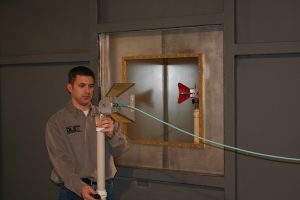
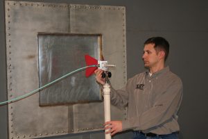
There is an ever-increasing demand for lighter, stronger, easy-to-manufacture and cost-effective shielding solutions.
Jack Prawica and Jereme Irwin
DLS Electronic Systems, Inc., Wheeling, IL, USA
As we move into the 21st century, there is a demand for stronger, lighter, less expensive, and environmentally friendly, RoHS-compliant* conductive materials. Many industry insiders hope to replace aluminum, steel, and copper with conductive fabric and composite materials. According to Boeing, as much as 50 percent of the new 787s primary structures will be made of composite materials. Also, the military is starting to use tactical shelters made from conductive fabrics.
Another reason for the increased interest in composite materials is the sharp increase within the last 10 years in cell phones, PDAs, pagers, and other electronic devices. Gratifying our need to stay connected is becoming easier with each new product that is released. Along with this abundance in electronic technology, come the need for shielding and the ability to limit the amount of RF energy being intentionally or unintentionally emitted or received by such technology. In the past, metal was used as the primary method of shielding. Today, there is an ever-increasing demand for lighter, stronger, easy-to-manufacture, and cost effective shielding solutions. The shielding industry as a whole has realized this imperative and now offers a variety of products. Designs for all of these products share a common goal—either to reduce unintentional emissions or to protect equipment from such emissions. So how can you tell which of these products will effectively perform in your application? Of course, understanding the design philosophy doesn’t make it any easier to determine which device will work in a particular application. With so many standards and applications available, it is important to consult a testing agency that offers both shielding effectiveness testing and the experience of knowledgeable NARTE engineers. The testing agency or laboratory is the organization that actually performs the test and records the data.
BACKGROUND: SHIELDING EFFECTIVENESS STANDARDS
Shielding Effectiveness (SE) is the ratio of a transmitted signal received without the shield to the signal received with the shield (insertion loss) after the shield is place between the transmitting antenna and the receiving antenna [1]. The need for shield effectiveness (SE) is not new. The original “Military Standard Attenuation Measurement For Enclosures, Electromagnetic Shielding for Electronic Test Purposes Method of MIL-STD 285”dates back to 1956 and initially covered up to 10 MHz. This standard has been replaced with the IEEE 299 1997 “Standard Method for Measuring the Effectiveness of Electromagnetic Shielding Enclosures.” The most recent (2005) draft version is expected to be released sometime in 2007.
This covers testing larger enclosures in a frequency range of 9 kHz to 18 GHz— with specific provisions figures as low as 50 Hz and as high as 100 GHz. Several other shielding standards have been published as well. MIL-DTL-83528C, 2001 “Gasketing Material, Conductive, Shielding Gasket, Electronic, Elastomer, EMI/RFI Methods” utilizes a radiated testing technique for gaskets that covers 20 MHz to 10 GHz and can be extended. The SAE ARP 1705 standard for testing gaskets dates back to the early 1980s. It is a fairly repeatable test using a conducted testing method that utilizes transfer impedance; however, it is limited to about 700 MHz and does not take into account near field/far field effects. The IEC 61000-4-21, 2003 standard covers shielding effectiveness using the reverberation chamber test methods and covers a frequency range from 200 MHz to 18 GHz. As technology changes, the need to update old and to develop new standards is unrelenting. For example, an IEEE 299 Working Group has been formed to investigate different test methods for obtaining SE for smaller enclosures (i.e. 0.1-m cube and smaller).
It is very important to understand the design of the product to be tested, its application, and its frequency. With this understanding in mind, a tester can narrow in on the advantages and disadvantages of each standard and can choose a specific test methodology, or even tailor one to meet the product’s specific needs.
Once the standard and testing method are determined, the tester must find an appropriate shielding enclosure for testing. The shielding enclosure, as shown in Figure 1, is a structure with an interior protected from the effects of an any exterior electric or magnetic field. Conversely, the enclosure protects the surrounding environment from the effects of electric or magnetic field generated internally. A high-performance shielding enclosure is generally capable of reducing the effects of both electric and magnetic field strengths by one to seven orders of magnitude depending upon frequency. An enclosure is normally constructed of metal with provisions for continuous electrical contact between adjoining panels, including doors.

SAMPLE EXPERIMENT
In this sample experiment, we will explore the shielding effectiveness of materials in the frequency range of 1 to 40 GHz. One of the first measurements is the reference measurement with no material present in the test window. This step allows the tester to determine the dynamic range of the set-up.


The Dynamic Range (DR) is the range of amplitudes over which the receive system operates linearly. The DR is numerically equal to the difference between the maximum and minimum signal amplitudes when both terms are expressed in decibels. For a shielding effectiveness (SE) measurement, the most significant portion of the DR is that from the reference level to the noise floor. This measurement should be verified during the DR validation step of the SE procedures, and it represents the maximum SE measurable at that frequency with that particular equipment and settings. [1]
Figure 2 shows a dynamic range of at least 120 dB between 1 and 40 GHz. Determining DR requires two tests. The reference level test and the solid steel plate test plotted in Figure 3. The latter test helps ensure accuracy when testing the actual sample.
The set-up is extremely important if the end results are to be both repeatable and quantifiable. The antenna height and distance must be measured and kept stable during the duration of testing. At frequencies above 1 GHz, the antenna is very directional, and any slight movement of the antenna could cause a significant change in readings. It is important to document both the signal generator setting and the power level required to establish the desired level. The tester must be knowledgeable about the equipment being used. For example, testers must not overdrive the amplifier being used or saturate the measurement receiver.
Working in the GHz range and testing in a 12′ x12′ x 24′ chamber with a continuous welded steel partition has several advantages. First, testing is definitely far field. Also, most of the shielding effectiveness of the room is achieved via absorption. There are two main mechanisms of shielding for electric fields, reflection and absorption. Above 1GHz, the reflection loss decreases, and the absorption loss increases.
Figure 4 shows the shielding effectiveness of a solid steel and aluminum plate to be more than 120 dB up to 40 GHz. Also shown are data from a thin aluminum plate and carbon fiber material [3]. Research is being explored using a variety of fillers such as aluminum flakes, steel fibers, carbon fibers (shown), and nickel particles [4]
”]![Figure4 Figure. 4: Measured data of solid steel and aluminum plates– Used by permission of D.L.S. Electronic Systems, Inc. Also, available data for carbon fiber and thin Aluminum [3]](https://interferencetechnology.com/wp-content/uploads/2014/01/Figure4.jpg) Metals are the most common shielding material; and, as Figure 4 shows, they definitely provide the most effective shielding. Shielding approaching 120 dB is often necessary in the military, avionics, and automotive industries. Just how much shielding is 120 dB? For example, a 100-V/m signal would be reduced one million times to 100 µV/m. That extensive reduction is provided by 120dB of shielding.. Metal sheets are bulky and hence constant research and development is being done to find other shielding materials.
Metals are the most common shielding material; and, as Figure 4 shows, they definitely provide the most effective shielding. Shielding approaching 120 dB is often necessary in the military, avionics, and automotive industries. Just how much shielding is 120 dB? For example, a 100-V/m signal would be reduced one million times to 100 µV/m. That extensive reduction is provided by 120dB of shielding.. Metal sheets are bulky and hence constant research and development is being done to find other shielding materials.
Today, the design imperative is to reduce weight while retaining the mechanical strength and the level of electromagnetic shielding originally provided by metal. A number of alternatives are being researched. The avionics industry is making more and more use of woven carbon fiber composites. Polymer-matrix composites containing different types of fillers are also being explored for shielding.[4]
The common polymer matrix is electrically insulating and requires a special process for connecting the conductive fibers or particles. As conductive polymers become available with large combinations of fillers, the shielding effectiveness should increase. These conductive polymers allow the fillers to connect electrically without actually touching. The combinations and possibilities are endless, and look for expanded research on these materials as shielding demands increase.
For more information on shielding, visit our shielding channel here.
REFERENCES
[1] IEEE Std 10f0-2000, The IEEE Standard Dictionary of Electrical Terms.
[2] D.L.S. Electronic Systems, Inc., www.dlsemc.com.
[3] Rea Simon, Linton David, Orr Eddie, and McConnel Jonathon. “Electromagnetic Shielding Properties of Carbon Fibre Composites in Avionic System”, Microwave Review, June 2005.
[4] Chung D.D.L., Electromagnetic interface shielding effectiveness of carbon materials, 22 July 2000. Composite Material Research Laboratory, State University of New York at Buffalo, Buffalo, NY
* RoHS: The Restriction of Hazardous Substances Directive, July 1 2006. This Directive bans the placing on the EU market of new electrical and electronic equipment containing more than agreed levels of lead, cadmium, mercury, hexavalent chromium, polybrominated biphenyl (PBB) and polybrominated diphenyl ether (PBDE) flame retardants.
ABOUT THE AUTHORS
Jack Prawica, NCE, is the manager of the EMC testing laboratories for D.L.S. Electronic Systems, Inc. in Wheeling, IL. With 15 years of EMC testing and problem-solving experience, he has developed test procedures and has solved many EMI problems while dealing with the daily hands-on testing operations. He can be reached at jprawica@dlsemc.com, or visit www.dlsemc.com.
Jereme Irwin, NCE, is an EMC engineer for D.L.S. Electronic Systems, Inc. in Wheeling, IL. In his nine years of experience he has been involved daily with shield effectiveness testing, compliance testing, and EMI problem solving.
