Introduction
MIL-STD-461G, released in December 2015, added a test for Personnel Borne Electrostatic Discharge (ESD). Prior to this release, this type of test for electronic systems and sub-systems was managed at the system level under MIL-STD-464C released in 2010. Both of these standards contain similar requirements. MIL-STD-461G provides the details on testing and MIL-STD-464C established the compliance requirements without detail on how to verify compliance.
Prior to 2010, several ESD programs were in use by DoD to provide control measures and in some cases test methods to verify tolerance to ESD events were included. A couple of more common standards have been used and are still active:
- MIL-STD-1686 provided a ESD control program for non-ordinance electronic devices with reference to HBM (Human Body Model), MM (Machine Model and CDM (Charged Device Model). The various models are divided in classes based on sensitivity and marked to provide guidance on control measure implementation. ANSI and IEC standards for HBM evaluation are referenced but newer versions are used than cited in the current MIL-STD-1686C.
- MIL-STD-331D is the current standard for ordnance ESD control and includes a different model than personnel borne ESD. The difference is associated with control measures required for ordnance handling. The standard refers to JOTP 062 for ordnance ESD testing and requirements.
Background
From our high school years, physics training taught us about the atomic structure with electrons orbiting the nucleus and the net charge being related to the number of electrons relative to the number of protons. Materials with an unbound electron can release the electron to another atom with a small amount of energy. Contacting two materials can support the electron migration and separation of the materials may leave electrons trapped in another atom creating a net static charge between the two materials.
Depending on the forces present the static charge can reach very high voltage levels. If the voltage levels reach the point that the separating insulation allows the electron charge to recombine, a spark occurs bringing the two materials to a neutral charge. The static charge is created by many forces such as:
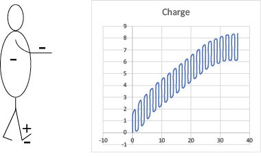
- Tribocharging where two bodies in contact are separated without allowing the electrons to return to their atoms. We encounter this from various sources such as walking across a carpet with each step supplementing our body charge. See Figure 1 for a conceptual sketch. The charge will dissipate through the air or we contact an object that provides the conduction path with a transient discharge. Note that moisture molecules in the air provide for dissipating the charge through the air more easily, so in a humid environment the charge accumulation is typically reduced.
- Electrostatic induction where an object is placed near a charged object and the field of the charged object causes electron redistribution. This charged object is present with an open circuit provides a voltage without current flowing.
- Particles bombarding an object causing surface charging. Electrons are dislodged and moved in the direction of the particle movement creating the charge differential. This charge is often associated with moving objects or wind driven water referred to as precipitation static.

Figure 1: ESD Charge Accumulation Concept
We realize that ESD events occur when a breakdown potential of the insulation is reached. Keep in mind that air is an insulator as well as non-conducting materials. The breakdown potential of air is approximately 80V/mil of distance. The breakdown potential for most insulating material is approximately 200V/mil of thickness. So, based on these approximations, a 100 mil air gap or a 40 mil thick insulator should prevent a discharge with an 8kV charge. Damage to an insulator if subjected to a discharge can produce small “pin-holes” and the insulator becomes an air gap with significantly less insulating properties.
CS118 Calibration Verification
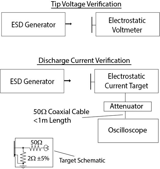
As with most tests in MIL-STD-461G, CS118 begins with the calibration verification or signal integrity check. Figure 2 provides a general configuration for the calibration verification with two different checks to be accomplished.
The ESD generator tip voltage is checked with an electrostatic voltmeter. The ESD generator is set for 2kV and the tip is placed at the measurement distance specified for the particular electrostatic voltmeter being used. Most electrostatic voltmeters have a guide or light convergence method to aid in placing the sensor at the correct distance. The voltmeter displays the measured voltage. The tip voltage tolerance is 10%. The tip voltage is repeated for each potential test voltage (4kV, 8kV, 15kV). If the tip voltage is not within tolerance correct the issue and redo the calibration verification.
The discharge current waveform is the second part of the calibration verification. Figure 2 incudes a configuration drawing for the discharge current check with the target schematic. The ESD generator is charged to the 8kV in the contact mode for the discharge current waveform check.

Figure 2: CS118 Calibration Verification Configurations
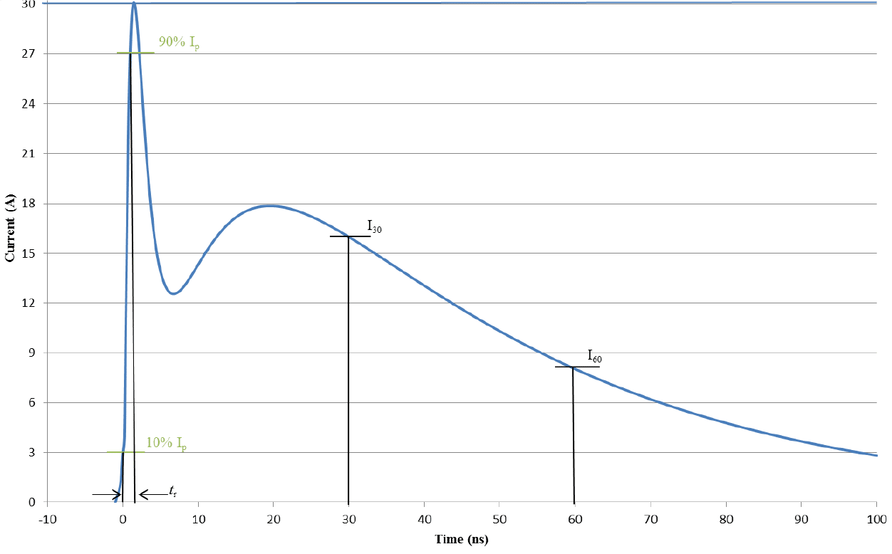
Set the oscilloscope to capture the waveform and place the ESD generator contact tip against the target plate. Trigger the discharge and review the captured waveform for compliance with the standard. The waveform shape is shown in Figure 3 and detailed parameters are provided in Table 1 . Note that the target design is the same as used for IEC 61000-4-2 testing standard.

Figure 3: Discharge Current Waveform

Table 1: Discharge Current Waveform Parameters
CS118 Test
The test configuration for ESD testing uses the standard configuration without tailoring. This differs from the customized ESD configuration called out in the similar IEC standard, so if you are familiar with IEC testing, pay attention to this difference.
Connect the ESD generator ground strap to the EUT’s chassis ground point. Only contact discharge at 8kV is required for conductive surfaces. Set the ESD generator to the test voltage and set for contact discharge. Apply 5-positive and 5-negative discharges while monitoring the EUT performance for indications of susceptibility.
Air discharge testing is applicable to test points where a contact discharge cannot be applied. Set the test voltage at 2kV for air discharge tests and apply 5-positive and 5-negative discharges to the test point. Note that discharges may not occur for each test point, but a residual charge could be present. Use a discharge conductor routed through a 1 M resistor to ground to remove the charge between discharge applications. After testing each point at the 2kV level repeat testing at each of the higher test levels (4kV, 8kV, 15kV) to determine compliance.
The air discharge is accomplished by moving the ESD generator air tip toward the test point at a rate up to 0.3 meters/sec until discharge or contact to the test point occurs. During test maintain a perpendicular orientation between the tip and the test point.
Test points should include locations likely to be contacted by the operator during normal use. The standard states that “test points to be considered shall include the following locations as applicable: any conductive or non-conductive points in the control or keyboard area and any other point of human contact such as switches, knobs, buttons, indicators LEDs, seams slots, grilles, connector shells and other accessible areas. As a minimum, each face shall be included.” Recall that air serving as the insulator has a lower breakdown voltage that insulating material so be sure to include ventilation openings as test points.
Earlier in configuring the test, the ESD generator ground strap was to be connected to the EUT chassis. Nothing is mentioned about this connection for equipment with an ungrounded chassis such as portable or battery powered units. In these cases, the EUT generator ground strap would be connected to the test location ground reference plane. Also note that residual charge removal between discharges is very important to prevent over-testing from charge accumulation.
Summary
ESD events are common and often are not noticed where the event occurs with low voltage levels but still can produce defects in sensitive circuits. A good control program is necessary to minimize issues stemming from ESD. Factories where circuit exposure is normal incorporate many controls and continually verify that the control measures are followed.
Prevention of charge accumulation is a control measure that may be built into the product or installation. Maintaining conductivity between items provides the path for electrons to recombine and neutralize the charge. Providing a means to discharge with the unit allowing the personnel borne charge to be dissipated to a point not subject to damage.
Product testing allows us to have confidence that our devices have a reasonable ability to tolerate ESD and continue to perform as intended. This test addition to MIL-STD-461G provides a logical location for this evaluation and it provides the detailed test instructions to verify compliance.


