by Kenneth Wyatt
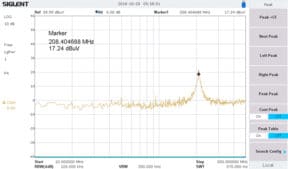
Cables are one of the key metallic structures on a product that can act as an antenna and couple energy, causing radiated emissions and possible compliance test failures. This has been discussed extensively in the literature on product design for EMI compliance. In many cases, they can resonate at their half-wave frequency and actually amplify any harmonic currents traveling along the cable shield near that resonance (or higher-order resonances). Very often, you’ll observe several broad resonant peaks in the emissions profile of a product under test.
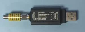
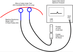
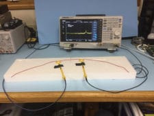
One easy and quick way to characterize the resonant frequency of cables and wires in a product or system is to inject harmonic energy into the cable and measure the actual resonances. We can do this in a controlled manner by using a harmonic comb generator. In this case, we’ll use the new Picotest Labs Model J2150A, which can produce a multitude of harmonics at several clock frequencies.
The J2150A includes five different user-switchable modes (see Figure 1):
- Stepped (modes 2 through 4)
- 1 kHz impulse
- 100 kHz impulse
- 1 MHz impulse
- 10 kHz square


- André and Wyatt, EMI Troubleshooting Cookbook for Product Designers, Appendix F (“Measuring Resonant Structures”).
- Picotest: http://www.picotest.com
- Siglent Technologies: http://www.siglent.com
- Beehive Electronics: http://www.beehive-electronics.com


