Studies show that Li-Zn ferrites can successfully suppress EMI
N.C. Joshi, S.S. Islam, Ph.D., Jamia Islamia University Jamia Nagar
Anjali Verma, Ph.D., Indian Institute of Technology New Delhi, India
Recent technological development has been characterized by an unprecedented proliferation of digital technology in information and communications equipment. The worldwide acceptance of portable, digital devices has created our present “information society.” A concomitant of this rapid development is an environment literally crammed with the electromagnetic signals that these devices create. Other results of the new information age include real concerns regarding the effect of this electromagnetic radiation on the human body and the increased likelihood of noise affecting other electronics.
Electronic noise can result in anything from a trifling nuisance to catastrophe if emergency, transportation, or medical equipment is affected. In any case, it is undesirable and must be controlled. This demand for superior suppression of noise has increased dramatically as a result of several factors, including the higher switching rates of power supplies and the more stringent requirements imposed by standards bodies throughout the world.
Equipment noise can be either internal or internal in origin. When a problem arises, steps must be taken to isolate the cause. The receiver must be identified and the source must be determined. Ideally, the noise should be reduced to an acceptable level without impacting the essential information being transmitted. Separating the emission source from the receiver is another acceptable alternative. It is also economical because the signal strength of the radiated source diminishes by the square of the distance to the receiver.
Still, when used judiciously, a common mode filter reduces both the conducted and radiated emission noise caused by the switching devices in the circuit. In fact, choosing the appropriate filter for noise absorption is vital to dealing with transients and to achieving high frequency conducted immunity at the input of the power supply.1
Implementing EMC measures is very cost effective at the beginning of the design process. All effective EMC techniques should be employed. Grounding, shielding, and filtering techniques are widely used and are successful in controlling EMI. Ferrite is increasingly used to control EMI and in EMI retrofits as the design nears completion. EMI suppression ferrite provides a cost-effective means of reducing common and differential mode electromagnetic noise. These ferrite cores are most frequently used to suppress common mode EMI on the internal and external cable assemblies of electronic equipment. By decreasing the level of EMI radiated by internal cables, ferrite cores can reduce both expense and the overall amount of shielding needed.
Ferrites are magnetic semiconductors. Both semiconductors and magnetic material exhibit interesting properties that can be used in electronic devices. Generally, ferrite material is used in the form of toroids, or high frequency beads. The impact of various design parameters should be considered when selecting materials. Such factors as permeability, Curie temperature, magnetic saturation, resistivity, and impedance are particularly relevant in EMC design.
Experimental Procedure
In the present study, the compositional formula of the series, namely Li-Zn,2is based on the generic formula:
Li0.25-x/4 Zn0.5-x/2 Mn0.1 Fe2.15-x/4 O4 (1)
Analytical grade raw materials in the form of oxide/carbonate of lithium, zinc, manganese, and iron are used for processing the ferrites. To avoid escape of lithium at high sintering temperatures, a small quantity of Bi2O3 (0.5 wt. %)3 was added in the initial mixing as a sintering aid. The materials were thoroughly mixed using the standard wet-ball milling technique. The material calcined in normal atmosphere at 750° C after four hours. A few drops of polyvinyl alcohol (2% solution.) were added to the calcined powder as a binding agent. The dried powder was pressed into circular discs and toroids (with an outer diameter (OD), inner diameter (ID), and height (H) of 28, 12, and 9 mm, respectively) by applying 5 ton/cm pressure.2 The samples were further sintered in the air atmosphere at 1050° C for four hours. The heating rate was kept at 40 C/minute and normal air cooling was followed.
Measurement Detail
The x-ray diffraction patterns of all samples were obtained using a Rigaku Geiger flex 3-KW x-ray diffractometer (XRD). Density of the sample was measured using the Archimedeas method. Saturation magnetization was measured with a vibration sample magnetometer (EG&G Princeton Applied Research model 155). The Curie temperature was measured by the arrangement detailed in Soohoo.4 The impedance and inductance were measured using the HP 4294 & HP4284 Impedance Analyzer. Insertion loss measured using R&S test receivers (ESH3 335.8017). EFT was generated by EFT simulators made by Keytek. The density of the ferrite material is shown in Table 1. The porosity measured 4.6 percent. It shows that the material sintered properly. The ferrite material, therefore, must have a high Curie temperature (Tc) and high magnetic saturation (Ms).

The high Curie temperature and high magnetic saturation show that Li-Zn ferrite material is a suitable magnetic material. The DC resistivity of Lithium-Zinc ferrite measured by using a two-probe method at ambient temperature was found to be 5.8 x 10⁶ Ohm-cm. A high resistivity is indispensable, especially for avoiding short circuits when the winding sits directly on a non-coated core. It also reduces eddy currents at high frequency.
The magnetic properties of ferrites make them a logical choice for solving EMI problems associated with high-speed electronic circuits. When properly selected, ferrites can absorb unwanted signals without interfering with the normal operation of the circuit.
One of the most important properties of soft magnetic material is magnetic permeability. Magnetic permeability is a measure of the degree to which a material modifies the local flux of an intersecting magnetic field. The application of a small magnetic field to a ferrite can result in large magnetic flux densities as it creates an alignment of the magnetic dipoles present in the material. The process of “magnetic moment alignment” results in both energy storage and loss; thus permeability is commonly expressed as a complex number. The permeability of a ferrite is a function of material characteristics, such as microstructure and chemical composition, as well as operating conditions, such as temperature, frequency and strength of the applied field, and the presence of static and non-signal field (DC bias). At low frequencies at the low end of the radio frequency spectrum, the storage component dominates. However, as the frequency of the applied field increases, the dominant storage component falls off, and the lossy component become increasingly important.
Ultimately a frequency will be reached at which the lossy component reaches a maximum. This condition is known as magnetic resonance. Above this frequency, the magnetic dipole can no longer follow the applied field.
The real and imaginary permeability varies with frequency as shown in Figures 1 and 2 . Figure 2 illustrates that at 110 MHz, the imaginary part of permeability is more than 100. It shows that Li-Zn ferrite is a wide bandwidth ferrite. At low frequencies, a ferrite inductor is characterized by low loss constant self-inductors, in which µs´ is highest. The suppression core is largely inductive and rejects the EMI signal to the source. At high frequency, where µs˝ becomes a more significant parameter, the inductor shows high impedance. It becomes resistive to dissipate interfering signals rather then reflecting them to the source. Figure 2 also indicates that the resistive part dominates above 1 MHz. A lossy material will show a smooth variation of impedance with frequency and real wideband attenuation.5
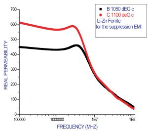
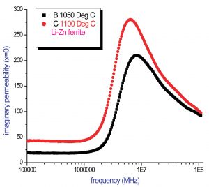
Variations of impedance with the applied frequencies were measured and are shown in Figure 1. Equation 2 represents the series impedance and complex permeability. The impedance (Z) of a ferrite suppression core is a combination of the intrinsic material characteristics—µs´ and µs˝, the square of the number of turns (N), and the ferrite core dimension.
Z = jw Ls + Rs = jw (µs´-µs˝) Lo (2)
where
Lo = 1.17N2 H Log10 OD/ID 10-9 (H) (3)
In Equation 2 dimensions are given in inches.6
Once the behavior of the material vis-à-vis impedance vs. frequency is known, the impedance may be improved further in two ways— viz. by increasing the core dimension and the number of turns (Figure 3). In Equation 3, doubling the height (H) will double both the volume and the impedance. Simply doubling the core volume by changing the OD and ID will increase the impedance by approximately 40%.7

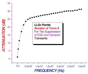
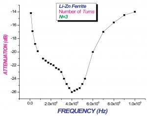
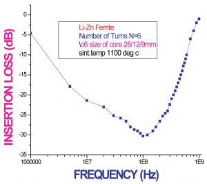
The performance of a ferrite core is often characterized using an insertion loss curve. The insertion loss of Li-Zn ferrite was measured, with an input and output impedance of 50 ohm, and with 3, 6, or 8 numbers of turns (Figures 4, 5. and 6).
The insertion loss also depends on source and load impedance and increases with the frequency. Clearly, insertion loss is not determined solely by product parameters such as impedance.6Consequently, insertion loss can be considered a significant point of comparison between ferrite devices, but it is not clearly predictive of the attenuation in a given application. The insertion loss is expressed logarithmically in Equation 5, in a 50-ohm/50-ohm system:
IL = 20 log10 (Zg+ZL+Zs)/(Zg+ZL) (4)
where
Zg = Noise source
ZL = load
Zs = the impedance of ferrite for a system 50 Ω/50 Ω.
Insertion Loss (IL) = 20 Log10 [1+Zs/100] (5)
The insertion loss graphs (in Fgures 4, 5, and 6) shows that an Li-Zn Ferrite is wide bandwidth ferrite for the suppression of electromagnetic noise. The resonance peaks for N=1 (600 MHz), N=3 (300 MHz), and N=6 (100 MHz) show that the ferrite is suitable for the suppression of various parameters of electromagnetic interference such as conducted noise (above 1 MHz), radiated emissions, immunity parameter electrical fast transients, electrostatic discharge, and damped oscillatory waves.
Application for Suppression EM Noise
A ferrite core numbers of turns = 6 in common mode is used at the input of the power supply (230/2 A) of a currency counting machine. The core insertion loss in this frequency band is >-25 dB as shown in Figure 6.
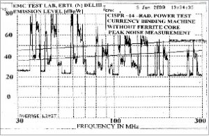
The function of the ferrite core is to absorb the electromagnetic interference at certain frequencies with the currency counting machine. The electromagnetic noise spectrum of the currency counting machine is measured as per CISPR 14-1. The power cord acts as an antenna for the radiation of electromagnetic noise (30 MHz to 300 MHz). A spectrum analyzer and an absorber clamp are used to measure the noise (Figure 7). It shows that the noise exceeds the regulatory limit. The Li-Zn ferrite core is installed in the currency counting machine, but the peak emission measurement still exceeds the limit (Figures 8 and 9). Such results call for an average and quasi-peak analysis of the peak emission that exceeds the average and quasi-peak regulatory limits The best solution is to achieve the maximum Impedance within this range.

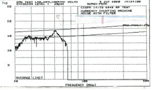
Now, the quasi-peak and average noise measured and observed are below the regulatory limit line. These results show that the Li-Zn ferrite core is effective in suppressing the EMI and a alternative material for the suppression the noise.

To suppress the EFT8 in electronic equipment, the effect of Li-Zn ferrites has been studied in a microprocessor-based energy meter that is energize at 230 Vrms and in a taxi fare meter.
The energy meter is completely non-functional at 400 V (EFT/Burst). It should be observed that with the number of 6 turns in common mode at the input of the power supply, the ferrite suppresses the EFT8, 9 up to 5.5 kV in the microprocessor-based energy meter.An electrostatic discharge can create severe problems in an electronic circuit. The ESD first converts into the current and generates a wide bandwidth (about 1-300 MHz magnetic field). This field creates a malfunction and sometimes damages the electronic device. The Li-Zn ferrite core with 6 and 8 numbers of turns in common mode provides very high attenuation in the entire spectrum of electrostatic discharge. The ferrite core may be used to suppress the ESD.
The damped oscillatory transients are induced in the low voltage circuits by phenomena in the high voltage or medium voltage networks (switching phenomena, faults, etc.). These types of transients are characterized by high frequency and high voltage (2.5 kV–1 MHz) and by wide bandwidth in the frequency range between 1 and 10 MHz. The electronic relay used in a HV/MV installation badly affected by the transients. The Li-Zn ferrite with an insertion loss with 8 numbers of turns (Figure 4) is used at the input of the power supply and suppresses the transients effectively.
Conclusion
Our experimental results revealed that Li–Zn ferrite can be used as an alternative device to suppress electromagnetic noise. The material sintered at 1050° C, a comparatively low figure as compared with Mn-Zn and Ni-Zn ferrites, which are sintered at 1200° to 1400° C. The ferrite material was sintered at 1050°, 1100°, and 1150° C to determine the effects of impedance vis-à-vis frequency. In fact, no significant difference was observed. The insertion loss graph shows that material is suitable for use in the suppression of conducted emissions, radiated emissions, and immunity parameters.
References
- David Morgan, A Handbook for EMC testing and Measurement.
- http://www.emsstg.com/ferrite/mmat_lithium.asp
- Pran Kishan, D.R. Sagar, S.N. Chatterjee, L.K. Nagpaul and Nitendar Kumar , adv in Ceramics, vol .15 ,507, 1986.
- R.F.Soohoo, Theory and applications of Ferrites. (Prentice-Hall ,Englewood Cliffs, N.J, 1960) p. 252.
- Snelling, E. C., Soft Ferrites, Properties and Applications, 2nd . Butterworth, 1988.
- “Soft Ferrites for EMI Suppression” Technical Note Phillips Magnetic Products.1988.
- “How to Choose Ferrite Components for EMI Suppression,” 14th Edition Technical information of Fair–Rite Products Corporation ,USA.
- Testing and measurement techniques-Electrical Fast transients / burst immunity test as per IEC 61000-4-4.
- Michel Mardiguian, EMI Trouble Shooting Techniques, MacGraw Hill.
N.C. Joshi studied physics at the Kumaon University, Almora, Uttrakhand, India and specialized in electronic physics. After receiving a baccalaureate degree in 1984, Joshi joined the component testing Division of the Electronic Regional Test Laboratory (North) under the Ministry of Information and Technology, New Delhi India. At present, Joshe is working in an EMI/EMC lab as a scientist and is pursuing a Ph.D. in “Synthesis and Characterization of Li-Zn Ferrite for the Suppression of Electromagnetic Noise” from Jamia Millia Islamia University, New Delhi. Joshe can be reached at ncjoshimala1@indiatimes.com.
S.S. Islam is currently a professor in the Department of Applied Sciences & Humanities and is co-ordinator of the M.Sc. Electronics Programme, Faculty of Engineering & Technology, Jamia Millia Islamia (Central University), New Delhi. He holds a Ph.D. in material science from University of Paris (France) and has contributed several research papers to international journals. His research interests include spectroscopic investigation of semiconductor quantum structures, high-speed nano-devices, and ferrites. Email : safiul_el@rediffmail.com.
Anjali Verma has been working on the synthesis of electroceramics, particularly ferrites both in bulk and in thin film forms, by wet chemical methods. Her current interests include nanoscience and nanotechnology. She has a number of research papers to her credit in recognized scholarly journals. She completed her doctoral work at the National Chemical Laboratory, Pune, India, and later joined the Indian Institute of Technology, Delhi in 1994. She has also held teaching positions at Bombay University. (Email: anjali_verm@hotmail.com.
