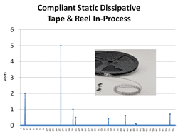
This article is the second part of “The Dip Tube,” which appeared in May in the 2010 Interference Technology EMC Directory & Design Guide. A digital version is available at www.interferencetechnology.com.
Over the past several years, both European- and U.S.-based organizations have sacrificed the traditional “internal auditing process” with over reliance on offshore contract manufacturers, distributors and suppliers to do the right thing. To compound the problem, organizations will accept supplier specifications as adequate proof in utilizing a product within their supply chain. Since it is now common for organizations to utilize Ultra-sensitive (Class 0) devices at ITRS Technology Roadmap for Semiconductors – Electrostatics – 2005
Reference 1. ESD Sensitivity Roadmap from ITRS.
Preventative protection measures against suspect counterfeiting during transport for electronic circuit cards and ESD sensitive devices must be considered. Dog food, medical products, jewelry, consumer goods and other items have made the news. Three industry sectors are of absolute concern: aerospace & defense, medical device and pharmaceutical drugs.
In this segment, the article will focus on two major packaging types that are utilized to protect Ultra-sensitive devices to and from the distributor by the device manufacturers, then received by the customer for in-process manufacturing.
To the surprise of aerospace and distributor alike, non-compliant or suspect counterfeit conductive or static dissipative JEDEC Trays and antistatic Tape & Reel (T&R) pose real issues during incoming inspection and manufacturing of Ultra-sensitive ESD devices. In the May edition of the Interference Technology 2010 EMC Directory & Design Guide, non-conformance of antistatic Dip Tube rails was illustrated to compromise compliant ESD sensitive components by using suspect counterfeit, non-conforming or recycled ESD packaging products. Several aerospace engineers stated that this problem had never been considered in developing a Suspect Counterfeit inspection process. In comparison to the pharmaceutical and medical device sectors, aerospace is a relative newcomer to the implementation of anti-counterfeiting measures.
In the 1990s, the semiconductor sector incorporated countermeasures to identify suspect counterfeit packaging and materials. By using innovative packaging engineering designs and advanced materials to protect ESD-sensitive devices, tampering and substitution was mitigated. Due to proprietary technology sets, many industry sectors do not share information. Whereas some major aerospace organizations may not employ packaging engineers, a major pharmaceutical company could have as many as 50 degreed packaging engineers on staff that develop innovative designs to prevent tampering.In the pharmaceutical sector, some packaging supplier machine centers produce fiberboard and corrugated packaging graphics of high lithographic quality.
It is not uncommon for machine centers to cost up to $10 million or more. For suspect counterfeit protective package using innovative materials, RFID antenna circuit lines can be preprinted onto engineered paperboard, post printed or applied during manufacturing. By identification of packaging vendors that supply both pharmaceutical and medical device sectors, the aerospace and defense sectors could reduce costs per unit, especially when the product is space bound and return material authorizations (RMAs) would have no value. Traditionally, the aerospace and defense sectors have relied upon packaging expertise from suppliers or distributors who rely upon their vendors for innovative ideas.
In most cases, this does not pose an issue with simple packaging schemes. However, with advanced suspect counterfeit mitigating technologies such as electrostatic shielding corrugated packaging, holographic labels and the real possibility of LEDs printed onto paperboard substrates [1] as countermeasures, a suspect counterfeiter’s efforts can be kept at bay (for now). It is not uncommon for unauthorized substitutions or replacement packaging practices to occur without customer knowledge.On 18-19 November 2010, a Suspect Counterfeit Aerospace & Defense materials and packaging course is scheduled for Oxford University School of Continuing Education. For details, see the ad at the end of this article.
“Repackaging ban most powerful tool to prevent counterfeiting in Europe”Phil Taylor, 24 Jun 2008 In-Pharmatechnologist.com“European pharmaceutical manufacturers stepped up calls for a blanket ban on repackaging of pharmaceuticals last week, suggesting that this would be the single most effective way to seal the supply chain for counterfeiting drugs.“As an industry we are prepared to make the necessary investment so that we can track and trace our products. But that will have no value if people are allowed to take and destroy our packaging,” he stressed.
Increasingly for the past few years, the author has consulted with both aerospace/defense and space agencies for supplier non-compliance. Products have been placed in quarantine, launches have been delayed and product failures with satellites have been identified. Even though requirements for correct procedures and validation methods are pushed down to the contract manufacturer, countermeasures by the aerospace OEM need to insure that a formalized material qualification process is in place. This process requires a customer to take physical measurements. A frequent occurrence with OEMs, however, is the reliance upon a vendor to resolve corrective actions without proper oversight. Resolution without corrective actions may not take place without verification. In 2008, for example, long-term storage issues had contaminated products for a launch. Because the space agency had very little expertise in packaging engineering disciplines, the issue lingered for months when third party packaging engineering expertise could have put the issue to rest within weeks.
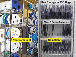
Figure 1a. JEDEC Tray being validated
Figure 1b. (left) Tape & Reel (noncompliant storage); (right) Tape & Reels in static shielding bags for compliance. (Courtesy of Frontier Electronics Systems Corp., OK, USA)
Antistat migration was found to be the source of the problem for the space agency. Moreover, there was very little evidence, if any, that the antistat wrap had been tested for contamination and undergone accelerated aging. In fact, the vendor’s product specification sheet appeared to be the only criteria for acceptance. Leadership in clearly defining an Anti-counterfeiting Roadmap must be driven down by the customer! In my opinion, distributor practices must be subjected to physical audits of packaging materials, not just processes, to insure supplier conformance. If a supplier does not have the necessary resources or “know how” to bring innovative methods to the table, the user must define requirements and physically audit the supply chain.
CASE STUDY: JEDEC Nonconformance
Will removal during inspection of ESD sensitive components cause failures if the JEDEC tray is noncompliant or suspect counterfeit? In Figure 2, the black JEDEC tray was not static dissipative and had a 2-point resistance (ANSI/ESD STM11.13-2004) of 6.2 x 10¹¹ ohms; this finding is insulative or above the limit of 1.0 x 10¹¹ ohms.The packaged components were also found to be suspect. Consequently, it was very unlikely that the suspect counterfeit JEDEC tray packaging was designed to be ANSI/ESD S541-2008 compliant. Thereafter, intimate contact with a metal tweezers tip and the leads of the surface mount device resulted in an ESD event at 561 volts (see Figure 3).
 Figure 2. 2-point resistance of JEDEC Tray (failed)
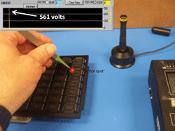 Figure 3. Non-compliant JEDEC Tray charged to +1kV and grounded with tweezers making contact to the leads of ESD sensitive devices to cause a spark as seen in red.
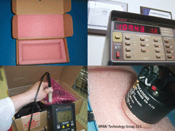 Figure 4. JEDEC Tray Box with non-compliant pink PE foam and failing bubble wrap.
The suspect non-shielding corrugated Lock Front Mailer with an antistatic Polyethylene (PE) foam insert measured insulative at 1.09 x 10¹² ohms and 1.2 x 10¹² ohms for the base and lid (Figure 4). The inner antistatic bubblewrap measured insulative at 1.1 x 10¹² ohms and 1.7 x 10¹² ohms. Both 2-point and surface resistance readings were insulative. Each measurement was taken between 50%RH to 53.3%RH. This finding is significant since testing for ANSI/ESD S541-2008 compliance or qualification requires 12%RH, +/-3%RH at 730F, +/-50F after 48 to 72 hours of preconditioning. European winter conditions can easily produce environments of 10 ohms at 50%RH and 1.3 x 10¹² ohms (failing) for 12%RH after 48 hours of preconditioning.The aerospace and defense engineer needs to understand that non-conforming or suspect counterfeit packaging materials are a major cause for concern. Compliant ESD sensitive components are at risk if the packaging was qualified by accepting a vendor’s specification sheet without validation by in-house or 3rd party testing. Consequently, one can expect the unexpected.JEDEC packaging may be subjected to charging during the box sealing or taping process. Therefore, a corrugated container should be electrostatic discharge shielding or the JEDEC tray needs to be placed into a metalized Type 1 shielding bag.
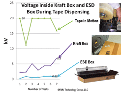 Figure 5. (top) Packing Tape off reel charging to over 20,000 volts; (center) 6.8kV penetrating a Kraft corrugated box with no shielding protection to cause all the microprocessors to fail; (bottom) Only 0.98kV penetrating the box while being taped in proximity to 80kV voltages where no microprocessors failed.
During the box sealing validation process, approximately 20 microprocessors inserted into a vacuum formed antistatic polymer insert were subjected to the taping process (see Figure 5). Because adhesion is important, large rolls of tape are positioned opposite the top and bottom box flaps in a conveyor system. Another school of thought is that the distance between the top and bottom of the corrugated container at a said distance offers enough space to withstand ESD events. This may have some validity in an ESD Protected Area (EPA) where charge can be controlled. However, the rolls of tape without ionization were measured over the measuring capability of a chopper stabilized electrostatic field meter at +20kV, blowing a sensor. Later, at 6 inches, using an industrial grade static locater, the voltage was found to be 80kV. The microprocessors were placed inside the vacuum formed insert and the Kraft (non-shielding) B-Flute Regular Slotted Container (RSC) was closed by hand. Peak voltage seen inside the box during the automatic taping process was measured at 6.8kV. As a result, all 20 microprocessors were non-operational. Later, 20 new prototype microprocessors were placed inside a validated static shielding (with an inner conductive liner) corrugated B-flute RSC where all flaps met. In this case, however, there were no failures observed after the taping process.
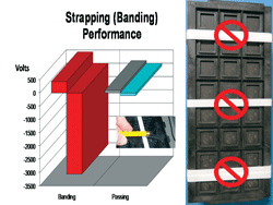
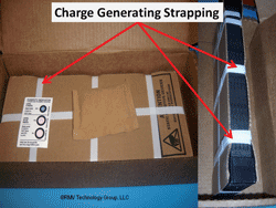
Figure 6. (top) Strapping under the corrugated pad in close proximity to ESD sensitive devices; (bottom) -3000 volts recorded for a JEDEC tray white strapping which did not use a corrugated shielding pad.
After undergoing ESD S20.20 training, the distributor identified a non-conforming JEDEC box (see Figure 6). The product was quarantined and evaluation of the strapping using a non-contact computer interfaced voltage probe system recorded a peak charge of -3000 volts. Unfortunately, strapping had been affixed to the JEDEC tray directly over ESD sensitive devices at 6 positions. The OEM should have inserted the JEDEC tray into a Type 1 Aluminum moisture barrier bag and then applied the strapping under ionization. Visual inspection of the JEDEC tray should alert receiving inspection that the package was non-conforming and also could be “suspect” counterfeit. Applying an ANSI/ESD S541-2008 compliant electrostatic shielding paperboard pad and shielding layer making intimate contact with static dissipative JEDEC trays would be an accepted minimal practice.
However, lack of sound ESD compliant safeguards made it necessary to place the JEDEC box in quarantine In short, ESD packaging engineering protocols and innovative design methods can be utilized to insure protection against suspect counterfeiting or supplier non-conformance. One practice worthy of consideration is the development of a change notification that lists detailed packaging engineering modifications and provides traceable testing results of the package. Customers need to be informed of countermeasure implementation.
For example, the use of RFID tags would constitute a sound protective package safeguard. Likewise, subjecting one’s supplier to a formalized qualification sequence for JEDEC trays reinforced with a certificate of conformance (COC) authentication can prevent suspect counterfeit or non-conforming ESD materials and packaging from being utilized in combination with Ultra-sensitive ESD devices.
TAPE & REEL PACKAGING ISSUES
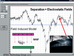
Despite claims that issues with Tape & Reel have been put to rest, supplier non-conformance, suspect counterfeit ESD sensitive devices and packaging present major problems in producing a quality product. Problems present themselves when a suspect counterfeit or non-conforming Tape & Reel package pose issues during the parts inspection process with ESD sensitive devices. The act of tape removal from the carrier can generate electrostatic fields that kill ESD sensitive devices upon contact with tweezers or during pick and place.
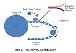 Figure 7. What a Tape & Reel looks like when mounted in the factory.
The separation process (see Figure 7) can be likened to pulling Scotch Tape from a dispenser if the cover tape is non-compliant. As seen in the previous section, packing tape was witnessed to charge over 20kV. To mitigate potential issues, subjecting the Tape & Reel to resistance validation per ANSI/ESD STM11.11-2006 (IEC 61340-2-3), ANSI/ESD STM11.12-2007 (IEC 61340-2-3) and ANSI/ESD STM11.13-2004 (2-point resistance) can lead to better yields.
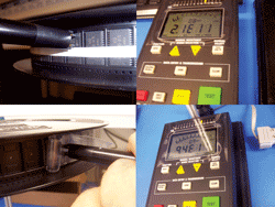
 Figure 8. (left) Concentric ring measurement of inside of the reel; (right) Using a 2-point probe to measure difficult to reach areas in the reel.
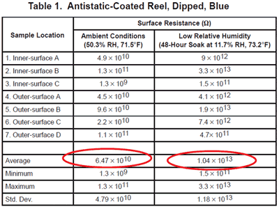
Figure 8 illustrates how an organization validates a static dissipative reel before incorporation into the manufacturing process. The lower left figure is a surface resistance measurement in accordance with ANSI/ESD STM11.11. To the right, one can see the use of a 2-point probe per ANSI/ESD STM11.13. As a result, the product failed at 11.7%RH and at 50.3%RH for a blue antistatic coated reel (Table 1). It is clear from the findings (see Table 11) that a topically coated antistatic reel exhibits humidity dependence as the results fluctuated from 50%RH to 11.7%RH for failing readings. Subjecting product to a formalized qualification sequence can prevent costly ESD related issues during manufacturing and assembly.
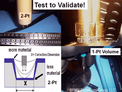 Figure 9. Using small profile resistance probe to measure inside the carrier cavities. Probe on the top is 2-point probe and the bottom right photo probe is 1-Point for volume resistance.
A package (see Figure 10) was received by incoming inspection. The QA distribution manager noticed that the Type 1 metallized moisture barrier bag had drawn a vacuum that would crush the components in the carrier tape. Upon review, the author found the bag to have three seams. This observation would be a red flag because an electrostatic shielding bag requires two seams. Electrical continuity is essential to insure charge bleed off. Consequently, the bag was tested for surface resistance on the inside and outside of the shielding structure as illustrated in Figure 11a.
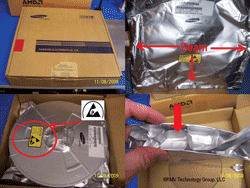 Figure 10. Non-conforming moisture barrier bag with 3-seams when 2-seams are required for ESD compliance. The bottom right photo shows a vacuum was pulled too much which crushes the devices. A trustworthy supplier would not pull an excessive vacuum. Thus, visual inspection to the knowledgeable incoming inspector would identify this package as suspect! (Courtesy of Ed Dimmler, PCX, Inc. QA &ESD Program Manager)
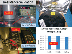 Figure 11a. Measuring a 3-seam suspect counterfeited bag for surface resistance which produced failing results.
The results in Figure 11a were failing for the inside and outside of the Type 1 bag.
 Figure 11b. Humidity Independent (IDP) moisture barrier bag.
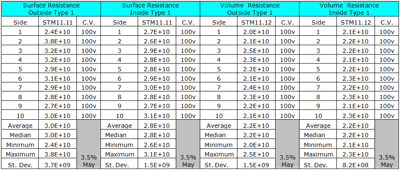
As illustrated in Figure 11b, six (6) conforming Tape & Reel Type 1 humidity independent (IDP) ESD Moisture Barrier Bags (MBB) were evaluated at 3.5%RH over 72 hours at 73.40F to simulate the environment inside a MBB when a vacuum is pulled before inserting a desiccant. A suspect counterfeit Type 1 bag may appear compliant, however, aside from a typical 3-seam appearance, the only way to verify compliance is by taking resistance measurements. Guidelines that a suspect counterfeiter will likely ignore can be found in MIL-PRF-81705D, w/AMENDMENT 1, 14 July 2004 for PERFORMANCE SPECIFICATION of BARRIER MATERIALS, FLEXIBLE, ELECTROSTATIC PROTECTIVE, HEAT-SEALABLE.
Table 1. RMV test finding for TI white paper, courtesy of Albert Escusa.
Table 2. Compliant Results at 3.5% RH for 72 hours of preconditioning.
Table 3. Surface Resistance & Volume Resistance.
Figure 12. 2-point resistance of the carrier cover tape (outside and inside)
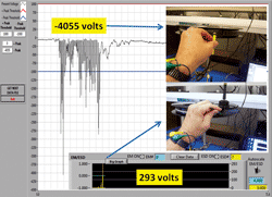
The results in Table 2 were favorable at 3.5%RH which represents an environment seen inside a moisture barrier bag after drawing a vacuum. If the bag looks suspect and tests as non-conforming (see Figure 11a), then one would test the cover tape as a validation step. As a result, at 55%RH, the cover tape (using ANSI/ESD STM11.13) produced an insulative reading of 2.1 x 10¹¹ ohms for the outside and 9.4 x 10¹¹ ohms on the inside of the cover tape (Figure 12). The next step is to see what happens to the cover tape upon separation from the carrier (see Figure 13). Separation generated a peak of -4055 volts. The reel was placed upon a grounded stand and contact between one of the component’s lead was made with tweezers while wearing a wriststrap. An ESD event of 293 volts is illustrated by the Novx antenna (see Figure 13).
Figure 13. Shows the charge of -4055 (top) on the carrier tape as captured by a yellow colored non-contact voltage probe and the corresponding ESD event of 293 volts (as captured by the black ESD event antenna) when a stainless steel tweezers makes contact with one of the lead of the ESD sensitive devices that the Tape & Reel is packaging.
The current discussion represents what could take place during the inspection and validation process by Incoming Receiving. One needs to consider if packaging used to protect ESD sensitive components is suspect counterfeit or non-conforming. The inspection and validation process of removing a device from a problematic package can lead to failures with Ultra-sensitive (Class 0) devices. In March 2010, the author gave a presentation at NASA Cape Canaveral titled “Non-compliant or Suspect Counterfeit Materials Can Lead to ESD Hazards and Long-Term Storage Issues.” Feedback from the aerospace community constituted a lack of awareness that suspect counterfeit materials and packaging were being utilized throughout the supply chain. The next phase will focus upon actual readings secured during an assessment at a DoD contract manufacturer’s Tape & Reel operation.
Figure 14. Charge separation of th carrier tape of -400 volts.
Despite the reel’s black appearance indicating a carbon loaded static dissipative or conductive material, the reel measured insulative (see Figure 15).
Figure 15. 2-point resistance of non-compliant or suspect counterfeit Reel
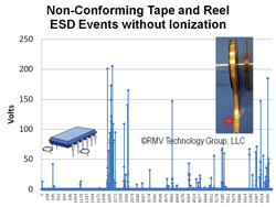
During actual production using a non-conforming Tape & Reel package (see Figure 16), ESD events were numerous. Even if the devices were found to be compliant, the non-conforming or suspect counterfeit Tape & Reel package promotes Triboelectrification leading to Field Induced Model Discharges. Suspect counterfeit packaging can cause production delays and component failure due to electrostatic discharge.
Figure 16. Non-conforming tape & reel carrier results during actual production and placement of ESD sensitive devices which generated many discharges with no ionization.
In contrast, a conforming Tape & Reel (see Figure 17) utilized in the manufacturing process did not produce significant issues and was under a +/-100 volt threshold as set forth in the company’s ESD program manual.
Figure 17. Using ionization with a compliant tape & reel, very low magnitude ESD events with rare occurrences took place.
In short, it appears that Tape & Reel packaging has been targeted for suspect counterfeiting. ESD packaging materials must undergo validation to rigorous standards to insure ESD compliance.
REFERENCES
1. Xth International Seminar on the Technology of Inherently Conductive Polymers, Progress in Light Emitting Polymer and Dendrimer Technology, 23-25 June 2003, Presentation by Cambridge Display Technology
2. Non-compliant or Suspect Counterfeit Materials Can Lead to ESD Hazards and Long-Term Storage Issues, Bob Vermillion, NASA QLF, Kennedy Space Center, 18 March 2010
3. Electronic Part Damage by Antistat Vapor, John Kolyer, Ph.D., Arie Passchier, Ph.D. and W. Greg Peterson, The Boeing Company
4. ESD from A to Z, Dr. John Kolyer and Watson, 2nd Edition
5. Mil Handbook 1686C-1995
6. Mil Handbook 263B-1994
7. EIA STANDARD
8. Packaging Materials Standards for ESD Sensitive Items, EIA-541, June 24, 1988, Appendix C “Triboelectric Charge Testing of Intimate Packaging Materials”
9. ANSI/ESD S20.20-2007 [IEC or EN 61340-5-1:2007 & TR 61340-5-2 © IEC:2007]
10. ANSI/ESD S3.1-2006 [EN 61340-5-1:2007]
11. ANSI/ESD STM4.1-2006
12. ANSI/ESD STM11.11-2006 [ANSI/ESD STM11.11-2006 [CEI IEC 61340-2-3]
13. ANSI/ESD STM11.12-2007 [ANSI/ESD STM11.11-2006 [CEI IEC 61340-2-3]
14. ANSI/ESD STM11.13-2004
15. ESDA Adv. 11.2-1995
16. Using An ESD Packaging Materials Qualification Matrix for Contract Manufacturing and Supplier Conformance, Sep. 1, 2006, Albert Escusa, Texas Instruments and Bob Vermillion, RMV Technology Group, LLC
17. Ed Dimmler, PCX Inc. for Suspect Counterfeit Tape & Reel and Type 1 Bag Specimen
18. Dr. John M. Kolyer, Ph.D., Rockwell International, telephone interview in 2004
19 The Charged Device Model & Work Surface Selection, John Kolyer and Donald Watson, October 1991, pp. 110-117
20. Humidity & Temperature Effects on Surface Resistivity, John Kolyer and Ronald Rushworth, Evaluation Engineering, October 1990, pp. 106-110
21. Military Handbook-263B-1994
22. Triboelectric Testing at KSC Under Low Pressure and Temperature, ESD Association Proceedings 2002, Dr. Ray Gompf, PE
23. ITRS Technical Requirements – Electrostatics, The ITRS is devised and intended for technology assessment only and is without regard to any commercial considerations pertaining to individual products or equipment
24. Intel Website, Moore’s Law25.
25. Intrinsically Static-Dissipative Reel, Texas Instruments, January 2004, Albert Escusa and Lance Wright from RMV Technology Group, LLC Lab work (Courtesy of Albert Escusa)
26. Carrier Specimens (Figure 9), Kurt Edwards, Lubrizol27. Novx Series 7000 Screen Capture with ESD Event Antenna, NOVX Figures 3 and 13
Special Thanks to Daibochi Plastics for running and providing six special Humidity Independent (IDP) Tape & Reel Type 1 Moisture Barrier Bag Specimens and Selected Illustrations and Data
Bob Vermillion, CPP/Fellow, is a Certified ESD & Product Safety Engineer-iNARTE with expertise in the mitigation of Triboelectrification for a Mars surface and in troubleshooting robotics or systems in aerospace, disk drive, medical device & pharmaceutical, automotive and semiconductor sectors. A co-author of several ANSI level ESD documents, Bob serves on the BoD with iNARTE and is a member of the ESD Association Standards Committee and conducts ESD Seminars in the USA and abroad. Bob is Chief Technology Officer of RMV Technology Group, LLC, a 3rd Party ESD Materials Testing and Consulting Company. You can reach Bob at 650-964-4792 or bob@esdrmv.com.


