Can you imagine a world without electronic devices? AR asks and answers this question in its new blog series: “Specifying RF/Microwave Power Amplifiers for EMC Testing.” Explosive growth in technologies like portable electronics, Internet-of-Things devices, and autonomous vehicles has led to a world full of electromagnetic interference. Efficient EMC testing is more critical than ever and is dependent on high-quality test equipment. Do you know how to select the proper RF/microwave power amplifier for your testing needs? Follow the series to learn how.
INTRODUCTION
Can you imagine the world without Electronic devices? Today’s electronic gadgets, machines and appliances have become an integral part of our lives. This is most apparent with recent developments in technology like drones, mobile internet, medical devices, Internet of Things (IoT) and autonomous vehicles. These technologies are used across military, aviation, automotive and commercial sectors. The result is a higher potential for harmful electromagnetic interference. This interference ranges from a small nuisance to complete product or system failures.
Historically, amplifier selection for Electromagnetic Compatibility (EMC) testing was based mainly on tribal knowledge and information scattered across the EMC industry. However, proper EMC amplifier selection is an important step in achieving required RF levels. Considerations are numerous. This application note provides the EMC test engineer or technician with the information necessary to make the proper decision. Areas covered in this selection guide include:
- Common EMC test standards
- Amplifier specification definitions
- Types of amplifiers
- Amplifier Accessories
- Systems
- Improving test efficiency and reliability – MT06002 Multi-tone
- Other considerations
- Summary
It should be noted that quality and support are of equal importance as technical features when selecting an amplifier. Downtime often means test lab throughput slows, thus impacting the lab’s profitability and customer schedules.
COMMON EMC TEST STANDARDS
EMC can be defined as the ability of systems and equipment to operate in their intended environments without suffering unacceptable degradation or causing unintentional degradation due to electromagnetic spectrum interference. Threats to a system can be both naturally-occurring and man-made and can be categorized into 4 main types of tests: Radiated Immunity, Radiated Emissions, Conducted Immunity and Conducted Emissions. The limits and levels used for these tests are defined in various standards and adopted by various organizations. It is imperative that products meet the requirements set forth in these standards because public safety, among other things, relies on the products to perform as intended.
Standards commonly used in sectors such as military, aviation, automotive and consumer are shown below. This guide will provide amplifier characteristics necessary to identify the appropriate amplifier for these standards. In many instances, the standard drives the selection of the amplifier. In addition, the end user often has unique requirements. End-user considerations are as important as industry standards.
Radiated Immunity
-
- IEC 61000-4-3: Commercial
- MIL-STD-461, RS103: Military Components
- MIL-STD-464: Military Systems
- DO-160, Section 20: Aviation
- ISO 11451, ISO 11452-2: Automotive
Radiated Emissions
-
- FCC Part 15
- CISPR 11, 22, 25, 32: Commercial
- MIL-STD-461, RE102: Military Components
- DO-160, Section 21: Aviation
RF Conducted Immunity
-
- IEC 61000-4-6: Commercial
- MIL-STD-461, CS114: Military Components
- DO-160, Section 20: Aviation
- ISO 11452-4: Automotive
Conducted Emissions
-
- CISPR 11, 22, 25, 32: Commercial
- MIL-STD-461, CE101, CE102: Military Components
- DO-160, Section 21: Aviation
AMPLIFIER SPECIFICATION DEFINITIONS
The foundation for proper amplifier selection is in understanding critical amplifier specifications. While amplifiers have a broad spectrum of specification parameters, there are a few key parameters to keep in mind relating to EMC testing. These parameters and their relevance to EMC testing are shown in Table 1: Amplifier Parameters.
| Parameter | Definition | Relevance |
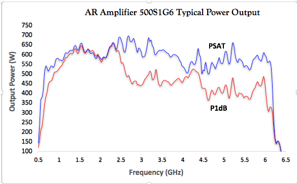
| Frequency Response | Instantaneous operational frequency band | Amplifiers are only specified to operate within this defined frequency band. Some solid-state amps will operate just outside of the band with significant power reduction (Figure 1), whereas TWTAs have much harder cutoff due to waveguide (Figure 2).
Figure 1 shows the performance of the AR Model 500S1G6 amplifier. This amplifier operates over the 700 MHz to 6 GHz frequency range. |

Figure 1: Example of Solid State Amplifier Output Power Over Frequency

Figure 2: Example of TWTA output power over frequency
| Rated Output Power | AR’s definition: Power generated by amp at 1.0 mW (0 dBm) input | Important power rating for applications where there are not strict linearity requirements (MIL / DO / Automotive). ‘Rated’ power is similar to (but not necessarily) ‘Saturated’ power. |
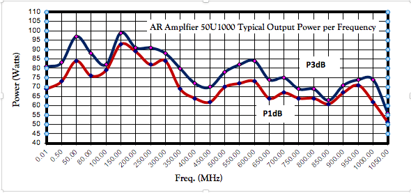
| Power Output @ 1 dB Compression | Power generated by amp at the 1 dB compression point | Important power rating for applications where there are strict linearity requirements (IEC / EN). Can be considered the top-end of linear power. Amp saturation increases after P1dB.
Shown in Figure 3 is an example of P1dB and P3dB levels for the AR Model 50U1000 amplifier. |

Figure 3: Example of P1dB and P3dB levels for the AR 50U1000
| Parameter | Definition | Relevance |
| Harmonic Distortion | Amplitude of harmonic distortion produced by amp | Majority of AR amps are -20 dBc @ P1dB, see Figure 4. Many test specifications require at least -6 dBc. See App Note #60. |

Figure 4: Example of Amplifier Harmonics
| Parameters | Definition | Relevance |
| Gain | The amplification factor, also called gain, is the extent to which an analog amplifier boosts the strength of a signal. Amplification factors are usually expressed in terms of power. | Many amplifier factors are a result of an amplifier’s gain, such as output power, size, and the power required to operate that amplifier.
Gain is called S21 using S-parameter terminology |
| Flatness | Flatness specifies how much the amplifier’s gain can vary over the specified frequency range. | Variations in the flatness of the amplifier’s gain can cause distortion of signals passing through the amplifier. |
| Efficiency | The ratio between the power of the output and total power consumption | Although Class A amplifiers are inherently inefficient, design techniques can improve amplifier efficiency as seen by AR’s amplifiers which are smaller and require less input power than other amplifiers equivalently rated. |
| Pulse Capabilities | Limitations on Pulse Width, Pulse Rate and Duty Cycle | Pulsed SSPAs and TWTAs produce higher-peak power than-CW power, but are limited in how much RF can be passed through amp. See App Note #39D. |
| Mismatch Tolerance | Ability of an amplifier to handle un-matched loads and thus varying amounts of reflected power | In EMC applications, especially at lower frequencies, transducers (antennas / clamps / etc.) can be a very poor match to 50 Ohms. Field reflections / standing waves can cause significant reflected power as well. During test, it is important to continue to deliver forward power as well as protect the amp from reflected power damage. See App Note #27A. |
| Pulse Capabilities | Limitations on Pulse Width, Pulse Rate and Duty Cycle | Pulsed SSPAs and TWTAs produce higher-than-CW power, but are limited in how much RF can be passed through amp. See App Note #39D. |
Additional Reading: ‘What Is EMC Testing?’
Next Topic:
Specifying RF/Microwave Power Amplifiers for EMC Testing – Amplifier Input & Output Requirements
