Authored by:
Gene S. Monroe, iNCE, NASA Langley Research Center, Hampton, VA
Bob Vermillion, CPP, Fellow, iNCE, RMV Technology Group, LLC, NASA Ames Research Center, CA
INTRODUCTION
Proper verification of an Electrostatic Discharge (ESD) Protected Area (EPA) relies heavily on the use of the National Fire Protection Association (NFPA) 5lb weights. These 5lb weights double as both a weight and as an electrode; this document will henceforth refer to this tool as a 5lb weight (Figure 1).
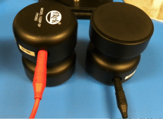
Figure 1. 5lb Weight with Electrode Polymer Pad on Bottom.
The 5lb weight has many uses, including providing enough weight atop a concentric ring for accurate and repeatable measurements of materials; it provides enough weight for measuring surface grounding and resistance of worksurfaces, stools/chairs, floors, and garments. The 5lb weight is one of the most used tools for verifying EPA compliance to a local ESD Control Program (CP).
The intent of this paper is to describe a verification procedure to validate the 5lb weight’s performance to the ESD Association (ESDA) and the American Society for Testing and Materials (ASTM) requirements as described in ANSI/ESD STM4.1/STM7.1 and ASTM F150.
The performance requirements for the 5lb weights include weight, conductivity, and flatness of its polymer pad. This paper describes the methods that the authors utilized for making these measurements and proposes adopting these procedures as a process for verification that may be used in place of a calibration requirement.
PURPOSE
Despite the importance of the 5lb weights to an ESD CP, there has been little discussion on how to formally calibrate these weights. This paper discusses performance requirements and test procedures to validate compliance based on the test parameter limits identified within the standards previously listed. The authors examined five test methods, explained in detail here and summarized in Table A. Data generated from the authors’ testing of multiple 5lb weights are provided in the appendices.
a. Why do 5lb weights rarely get calibrated?
The user may regard the 5lb weight merely as a weight, thereby unintentionally neglecting its electrical characteristics and the fact it will degrade over time. Because these characteristics are often overlooked, users may not realize that the weight is out of calibration, and, therefore, fail to have it calibrated.
Another often overlooked property is that of the 5lb weight’s polymer pad’s flatness, which, when uneven, will cause the 5lb weight to tilt. In addition, the lack of calibration of the 5lb weights could be due to calibration facilities not having a calibration procedure, as the procedure is proprietary and typically done by the manufacturer.
Additionally, the origin of the 5lb requirement is not clear; i.e., why not 4lb or 8lb? The best answer the authors were able to obtain was that it takes five pounds of weight to provide enough downward force to enable consistent and repeatable measurements. While test data that support this 5lb claim are unavailable, it is not relevant to this paper, and therefore, will not be challenged herein.
b. Electrical sensor characteristics
End user verification must include a requirement for electrode flatness for consistent and accurate electrode performance because, over time, the rubber electrode may harden, warp, or become damaged.
The authors used a printed circuit board (PCB) configuration from Prostat as the test fixture to measure flatness. The PCB has multiple resisters connected in parallel that act as a transducer to measure downward force over the surface of the PCB. A tilt in a 5lb weight, due to flatness error, will cause one side of the 5lb weight to be heavier than the other three sides, and will therefore be detected by the impedance measured not being equal. This imbalanced impedance will be noted when the 5lb weight is rotated from 0° to 90°, 180°, and 270° and measured at each orientation.
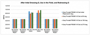
The impedance measurement should be 0.5MΩ; however, the authors were unable to find a defined level of tolerance in any industry standard to determine how much tilt due to an uneven polymer pad can be tolerated before the impedance measurement becomes unreliable. Thus, the authors decided to use the same level of tolerance that the ESDA uses for the grounding resistor used in wrist straps, which is ±20%. Therefore, it was decided that the measured impedances at each of the above-mentioned orientations should be 5E5 Ω ± 20% (0.4MΩ to 0.6MΩ). Any imbalance between the measurements taken at the four quadrant orientations that were within this range was found to have a negligible impact on the measurement’s accuracy when used in a system configuration that included two 5lb weights and one measurement apparatus (i.e., meter). An example of the unintended consequences when the impedance measurements are not within this range is described in Section 4.
VERIFICATION TEST METHOD DEVELOPMENT
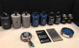
Figure 2. Various 5lb Weights and Test Hardware.
a. Equipment tested
In order to develop a verification method for 5lb weights, a variety of manufactured samples were tested. The manufacturers included 3M, Prostat, Transforming Technologies, and Trek Inc. (Figure 2).
b. Test methods, as listed in Table A
i. Test 1: Measure the weight
The weight requirement as listed in ANSI/ESD STM4.1 is 5lb ± 2.5%. The weight can be measured using a weight scale such as those used in post offices.
ii. Test 2: Measure internal resistance
The internal resistance for a single 5lb weight shall be less than 1kΩ. To measure this value, the authors used a Concentric Ring connected to one of a meter’s inputs via a circuit probe. The 5lb weight was positioned atop a Concentric Ring (Figure 3) with an additional circuit probe connecting the 5lb weight to the meter’s other input; adequate contact of the Concentric Ring’s outer ring to the 5lb weight’s polymer pad was essential.
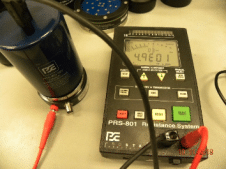
Figure 3. Concentric Ring Upside Down.
iii. Test 3: Volume resistance
To measure impedance through the weight as a modified volume resistance test method; the authors set the 5lb weight onto a conductive steel test platform as shown in Figure 4 (see test results in Appendix III). The maximum value was set at < 1.0kΩ.
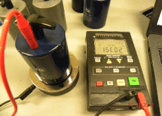
Figure 4. Volume Resistance 5lb Weight Test 3.
To measure flatness, the authors used the Prostat PRV-813 PCB test bed. The authors placed the 5lb weight onto the PCB fixture as shown in Figure 5. The impedance value, with tolerance set by the authors, was 5E5 Ω ± 20%.
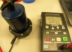
Figure 5. Measuring Flatness.
The process involved rotating the 5lb weight for four clockwise measurements using a PRV-813; the first at 0°, then 90°, 180°, and lastly 270°. Ideally, all four measurements are equal and thus verify perfect flatness; however, over time, those values will fluctuate as the polymer pad degrades. The end user must identify to what range of fluctuation these measurements can vary to ensure a level of flatness to accommodate an ESD CP.
v. Test 5: Measure the conductivity
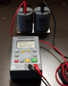
Figure 6. On a Stainless-Steel Plate.
Both ASTM F150 and ANSI/ESD STM4.1/STM7.1 set an impedance limit of <1.0 x 10³ Ω between two NFPA 5lb electrodes when measured on a metallic substrate (Figure 6). This measurement checks the conductivity of the rubber electrodes but not planar integrity (see results in Appendix I).
VERIFICATION TESTING
To develop a verification method for 5lb weights, testing of each method described above was conducted. The authors’ initial testing revealed that some of the older 5lb weights used in the measurement system were indicating that the materials under test (MUT) were failing due to measurements exceeding the allowable upper limit. To validate these measurements, multiple 5lb weights were used, which resulted in inconsistent measurements. The authors used a special dressing pad (i.e., emery paper type fine grit sandpaper) provided by one of the 5lb weight manufacturers to resurface and reset the impedances through the rubber pad; subsequently all the 5lb weights measured passing values for the MUTs. The authors then determined this wiping process will be part of the final Verification Procedure (see wiping procedure in Appendix VI).
VERIFICATION PLAN
Just as NASA and other entities have adopted routine verification measurements to validate instrumentation functionality in place of equipment calibrations, the test procedure below can be used for both calibration and verification of NFPA 5lb electrode resistance and flatness within the ESDA & ASTM prescribed limits.
- Verification Procedure: Routine verification ensures that precision equipment operates within the Original Equipment Manufacturer (OEM) specifications. Thus, it is important to obtain an accurate measurement of the 5lb weights as used and prior to being dressed for the verification procedures.
- Equipment Required for Calibration and Verification:
a. Resistance measurement apparatus
b. 2x conductive test bed (Figure 6)
c. 1x conductive test bed (Figure 4)
d. 5lb weight distribution device (Figure 5)
e. Dressing pad (Figure 8)
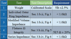
Table A. Test Parameters
- Each test listed in Table A summarizes various verification methods for 5lb weights. Series Impedance (#5) is conducted by measuring resistance between two electrodes side by side. Flatness Integrity (#4) constitutes the use of multiple resistors connected in parallel. Another flatness test, Outer Ring Impedance (#2), is the placement of an electrode atop the concentric ring to measure resistance. The Volume Impedance (#3) measures the resistance between the 5lb weight and a polished nickel-plated brass test bed. Finally, the weight measurement (#1) provides assurance that sufficient weight is applied to the surface being measured, for accurate and repeatable measures.
- After running these test procedures, clean the polymer pads using the special dressing pad.
- If the 5lb weight fails one of the tests listed in Table A prior to dressing the polymer pad, but passes afterward, then the local anomaly process shall be followed, such as: 1) Notify the projects where these 5lb weights were used during the time from previous verification to time of failure; 2) Recommend how to manage the associated risk.
If the 5lb weight failed both prior to being dressed and after being dressed, then the 5lb electrode shall be replaced and any affected projects will be notified.
CONCLUSIONS
The 5lb weight is arguably the most used tool for EPA certification, verification, and validation. However, the 5lb weight may be the least discussed tool by NASA, the DoD, and industry. Therefore, it can be argued that the 5lb weight is the least calibrated tool in both government and industry.
Proper verification of an EPA relies heavily on the use of the NFPA 5lb weight. The 5lb weight when used with a meter functions as an electrode with adequate downward force from the weight. This ensures enough contact area to measure the resistance to ground (RTG) and the resistance point to point (RPP) of various work surfaces throughout the EPA, including ESD-safe workbenches, flooring, garments, satellite shrouds, vinyl curtains, racking, and chairs. When used in this manner, both 5lb weight flatness and electrode conductivity must be assured.
The verification procedure as defined in the previous section ensures measurement integrity of the EPA surfaces for mission critical hardware.
In short, this document has defined five test procedures and test parameter limits and presented the test data obtained during this work in Appendix I-VI. Finally, the authors have presented a verification test procedure to validate the functionality of the NFPA 5lb weight, which in turn may be used to replace the traditional calibration requirement.
This document should therefore provide the ESD Program Manager with information that will enhance his/her ESD CP to include the quality assurance measurements by use of verified NFPA 5lb electrodes.
TEST LOCATIONS
There were two test locations; one in Virginia at the NASA ESD Lab at Langley Research Center, VA 23681, and the other in California at RMV Technology Group LLC Accredited ESD Laboratory at NASA Ames Research Center, Moffett Field, CA 94035.
REFERENCES
1. NASA-STD-8739.6, Implementation Requirements for NASA Workmanship Standards.
2. ANSI/ESD S20.20, For the Development of an Electrostatic Discharge Control Program for Protection of Electrical and Electronic Parts, Assemblies and Equipment (Excluding Electrically Initiated Explosive Devices).
3. ANSI/ESD STM2.1, For the Protection of Electrostatic Discharge Susceptible Items Garments-Resistive Characterization.
4. ANSI/ESD STM12.1, For the Protection of Electrostatic Discharge Susceptible Items Seating-Resistance Measurements.
5. ANSI/ESD STM4.1, For the Protection of Electrostatic Discharge Susceptible Items Worksurfaces-Resistance Measurements (Including Shelving and Mobile Equipment).
6. ESD STM7.1, The Protection of Electrostatic Discharge Susceptible Items Floor Materials Characterization of Materials.
7. ASTM D2240, Standard Test Method for Rubber Property-Durometer Hardness.
8. ASTM F150, Standard Test Method for Electrical Resistance of Conductive and Static Dissipative Resilient Flooring.
Appendix I
On Stainless Steel Plate (Side by Side) <1.0k Ω

Appendix II
On Concentric Ring Outer Electrode <1.0k Ω
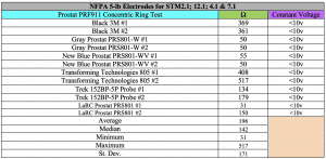
Appendix III
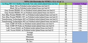
On polished nickel-plated brass test bed <1.0k Ω
Appendix IV
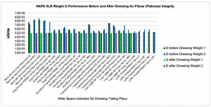
NFPA 5LB Weight Performance Before and After Dressing for Planar (Flatness) Integrity [5E5 Ω ± 20%]
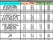
Note: LaRC readings were close enough to not require dressing of the pads
Appendix V
Appendix VI
Dressing NFPA 5lb Weights and After Use from Recent Data Center Floor Certification (5E5 Ω ± 20%)
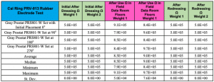
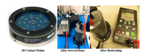
Figure 7
Appendix VII
The technique used is to wipe the pad in a uniform counterclockwise motion (Figure 8). This wiping pad is not to be confused with using alcohol on a Kimwipe® for cleaning the pads before use, but rather this wiping pad re-conditions the rubber pad attached to the base of the 5lb weight (See Appendix IV for results).
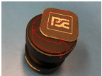
Figure 8. Dressing Pad
ABOUT THE AUTHORS
Mr. Gene Monroe received his BSEE from Old Dominion University (ODU), and his MSE from Virginia Commonwealth University (VCU). Mr. Monroe has been a NASA Civil Servant for 34 years. Gene is an iNARTE certified Electrostatics Engineer, an iNARTE certified Aerospace & Defense Engineer, and a RMV Technologies certified Aerospace & Defense Engineer. Gene is the NASA Agency Point of Contact (POC) for Electrostatics Discharge (ESD) and is the committee chairperson for the Interagency Working Group on ESD (IAWG-ESD). Mr. Monroe has been instrumental in aligning the NASA facilities to a likeminded ESD control program, which culminated with Agency ESD requirements being published in the NASA-STD-8739.6 document. The NASA Standard is a requirements document on all NASA contracts that build mission hardware.
Bob Vermillion, CPP, Fellow, is a Certified Product Safety & ESD Engineer-iNARTE® with proven subject matter expertise in the mitigation of Triboelectrification for harsh environments and troubleshooting of robotics, systems and engineered materials (displays, flexible electronics, 3D materials) for aerospace & defense, medical device, pharmaceutical, biotechnology, automotive and the electronics sectors. Bob is the co-author of several ANSI level ESD documents. Vermillion received the James A. Russell Lifetime Achievement Award for Packaging Engineering Innovation for Protection of the WarFighter in 2018 and one year later was inducted into the Military Packaging Hall of Fame. Since 2014, Bob is an active participant of the NASA ESD InterAgency Working Group (IAWG) as their Technical Authority for ESD and Founder and Co-Chair of the SAE G19 Sub-Committee for Packaging of EEE parts.
Vermillion is Founder and CEO of RMV Technology Group, LLC, a NASA Industry Partner and 3rd Party ESD Materials Testing, Training and Consulting Company. Bob Vermillion can be reached at bob@esdrmv.com or 650-964-4792. You may visit our websites at www.esdaerospacetraining.org and www.esdrmv.com and to see current and upcoming technology briefings for Government and Industry.
