By Lars Jacob Foged
The development of 5G cellular networks is well underway and requires a new approach to ensure accurate measurement of the antenna components. With flexible radiation patterns which are capable of adapting to the changing situations in mobile networks, the full characterisation of the Active Antenna System (AAS) in 3D space has been the focus of attention as a component for these new 5G networks. Lars Jacob Foged from MVG (Microwave Vision Group), explains the new approach to measurement and how fast and accurate AAS characterisation can be delivered.
The definition of ‘Massive’
A key part in 5G development, for both the user and network segments is Multiple-Input-Multiple-Output (MIMO) antenna arrays or “Massive MIMO”. “Massive” can vary in definition from AAS arrays with relatively few elements, through to more conceptual designs involving hundreds of antennas. Distributed amplification is a common denominator for both beam steering and full integration of the densely packed antenna elements. In order to characterize the AAS the collective performance must be determined in a calibrated Over-the Air (OTA) setup in which the spatial-directional power and sensitivity profile are measured. Consequently, the tests for much smaller mobile devices and the associated performance parameters in relation to these new tests are very similar.
AAS Performance
The parameters of interest for AAS performance are the directional dependent power and sensitivity performances in Far Field (FF) condition [1]:
• Effective Isotropic Radiated Power, EIRP(θ,φ)
• Total Radiated Power, TRP
• Effective Isotropic Sensitivity, EIS(θ,φ)
• Total Isotropic Sensitivity (TIS) or Total Radiated Sensitivity (TRS)
The EIRP(θ,φ) and EIS(ϴ,ϕ) are directional performance parameters that can be measured for a given direction of the antenna device in a calibrated Over-the-Air (OTA) measurement setup. The directional EIRP(ϴ,ϕ) is the radiated power weighted by the directional gain G(ϴ,ϕ) of the antenna. The TRP can be determined from a full sphere integration of EIRP(ϴ,ϕ) and associating isotropic gain to the antenna. Likewise, directional EIS(ϴ,ϕ) is TIS/TRS weighted by the directional gain G(ϴ,ϕ) of the antenna. TIS/TRS can be determined by integrating the EIS(ϴ,ϕ) over the full sphere and associating isotropic gain to the antenna.
A further parameter of interest is the polarisation characetristics of the AAS [2] as a mean to obtain polarisation diversity. Directional parameters such as EIRP(θ,φ), EIS(ϴ,ϕ) are often resolved in orthogonally polarized field vectors. Cross-polarization (X-pol) stands for “perpendicular” over intended polarization, which is called co-polarization (Co-pol).
Antenna Far-Field condition
A generally accepted criteria is to define the FF distance of an antenna as 2D2/λ, where D is the diameter of the antenna and λ is the free-space wavelength [2]. For electrically small antennas, such as antennas for mobile communication devices, measurement in FF condition is generally satisfied for convenient short measurement distances. However, even for moderate size AAS antennas, the measurement in FF condition puts unrealistic requirements on the measurement distance. Fig. 1 illustrates the elevation pattern of an 8-element array antenna at 2GHz ( BTS1940 from MVG) for different Near Field (NF) distances and the reference FF distance. The elevation pattern is not fully formed for any realistic measurement distance, as you can see in the images.
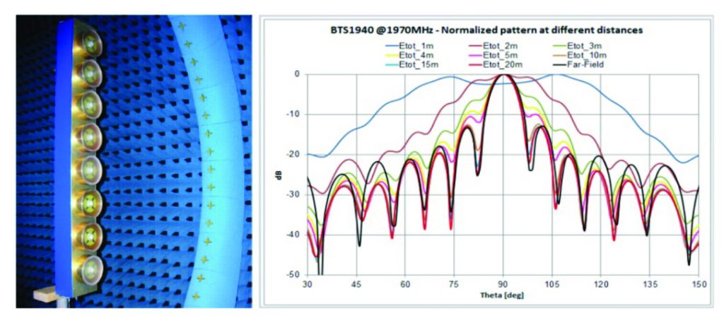
Fig. 1. Measured elevation pattern at 2GHz of an 8-element array antenna for different NF distances and FF.
The FF pattern of a given antenna can be measured directly in a Compact Antenna Test Range (CATR) [1, 2] or determined from NF to FF transformation using standard NF techniques [3]. NF measurements are often preferable for 3D performance scenarios, since they require physically smaller, less expensive, measurement setups and are generally considered faster and more accurate. Due to power conservation, AAS performance parameters can be determined at any distance from the device in a calibrated OTA setup. The difference in NF to FF gain of the antenna can be determined and compensated by standard NFFF transformation techniques [3].
Phase recovery
As the AAS antenna is an active device with highly modulated signals depending on the communication protocol, it does not provide a fixed phase reference, essential for NF to FF transformation. The recovery of the phase information requires a dedicated measurement setup. A common method is the holographic technique, which uses different combinations of the measured unknown signal with a stable reference signal. The preferred method here is an evolution of this approach based on the simultaneous reception of the reference and measured signals. A Phase Recovery Unit (PRU) has been designed to perform all the necessary amplification, filtering and signal combination for the accurate determination of the phase of the modulated signal.
Phase recovery measurement
The actual AAS antenna is emulated using a mobile phone with LTE protocol connected to an 8-element passive array (See Fig. 1), as external antenna and Fig. 2 illustrates the comparison of the measured amplitude and phase of the co-polar NF using phase recovery compared to passive measurement on the same antenna. You can see that the amplitude and phase correlation between the measurements works well.
When the measurement with phase recovery in LTE modulation was performed with the PRU unit in a 10MHz bandwidth around the 1940MHz centre frequency of the BTS antenna, the error introduced by the phase recovery technique was determined to be equivalent to a -45dB noise level.
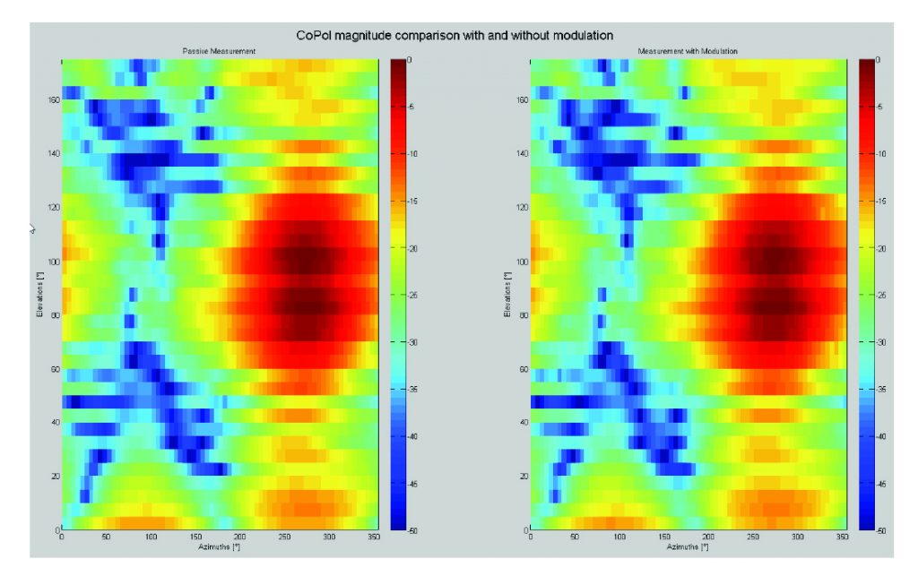
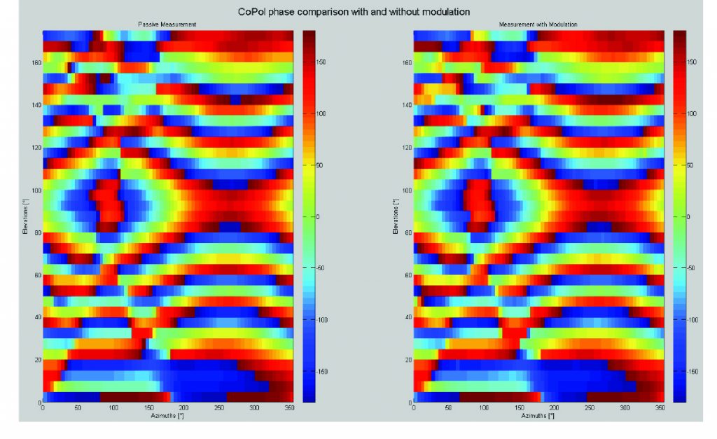
Fig. 2. Co-pol, NF of 8-element array antenna. Reference measurement (left) and active measurement (right) LTE protocol, using PRU. Magnitude (top), Phase (bottom)
NF validation
Validating the NF approach, a validation device with known EIS(ϴ,ϕ) and EIRP(ϴ,ϕ) is needed. Since the 8-element antenna and LTE device in this example are separable, the reference EIS(ϴ,ϕ) and EIRP(ϴ,ϕ) performance of the combined device can be determined from the antenna gain and the sensitivity / radiated power of the LTE device from a conducted measurement.
Using NF techniques for measurement of EIS(ϴ,Φ) of 8-Element array antenna for LTE protocol
The EIS(ϴ,ϕ) of the 8-element array antenna at 1940MHz using the LTE protocol has been measured in NF and compared to the reference scenario to validate the approach. The EIS(ϴ,ϕ) elevation and azimuth pattern of the reference and NF measurement, using the PRU unit in a 10MHz bandwidth around the 1940MHz centre frequency, are compared in Fig. 3. As expected, the pattern shapes are very similar in both azimuth and elevation. The ~1dB offset in measured sensitivity by the two methods is justified by the uncertainties relative to the NF measurements and the determination of the reference scenario. Range calibration and the sensitivity search accuracy for EIS measurement are considered the main uncertainty contributor for the near field measurements. Range calibration and sensitivity search accuracy for conducted sensitivity are considered the main uncertainty contributors for a reference scenario of this type.
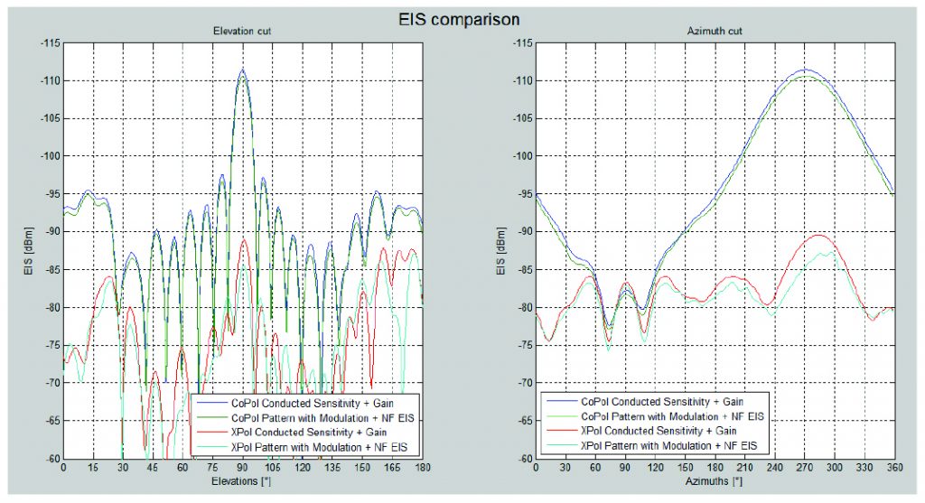
Fig. 3. Sensitivity pattern, EIS(ϴ,ϕ) of 8-element array antenna using LTE protocol.Comparison of direct measurement “Pattern with modulation” with reference “Conducted sensitivity”. Both orthogonal polarisation components are shown. Cross-polarization “Xpol” is perpendicular to the intended polarization “Copol” of the antenna.
Using NF techniques for measurement of EIRP(ϴ,Φ) of 8-Element array antenna for LTE protocol
In addition to measuring the receive EIS(ϴ,ϕ), the transmit EIRP(ϴ,ϕ) of the 8-element array antenna has been measured using the LTE protocol at 1940MHz. The EIRP(ϴ,ϕ) elevation and azimuth pattern of the reference scenario and the NF measurement, using the PRU unit in a 10MHz bandwidth around the 1940MHz centre frequency, are compared in Fig. 4. As expected, the pattern shapes are very similar in both azimuth and elevation. The ~0.5dB offset in EIRP(ϴ,ϕ) of the two measurements are justified by the uncertainties relative to the NF measurements and the determination of a reference scenario of this type.
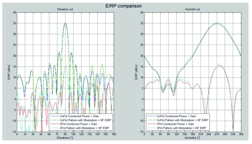
Fig. 4. Radiated power pattern, EIRP(ϴ,ϕ) of 8-element array antenna using LTE protocol. Comparison of direct measurement, “Pattern with modulation + NF EIRP” with reference “Conducted Power + Gain”. Both orthogonal polarisation components are shown. Cross-polarization “Xpol” is perpendicular to the intended polarization “Copol” of the antenna.
Advantages
The NF measurement technique has been demonstrated effectively in the measurement of performance parameters such as EIRP(ϴ,ϕ) and EIS(ϴ,ϕ) for active antennas such as AAS. It has been confirmed experimentally that the implemented PRU technique can reliably measure the phase in NF for modulated signal with large BW; such as, LTE and allow for accurate NFFF transformation. NF measurement technique makes this, in our opinion, for the accurate measurement and testing of 5G devices, the most advantageous way to measure.
REFERENCES
[1] Ericsson contribution, “On radiated testing of AAS BS”, 3GPP R4-132211, May 2013
[2] ANSI/IEEE Std 149-1979 Standard Test Procedures for Antennas.
[3] IEEE Recommended Practice for Near-Field Antenna Measurements, IEEE Std, 1720-2012
[4] L. J. Foged, A. Scannavini, N. Gross, F. Cano-Facila “Accurate Measurement of Transmit and Receive Performance of AAS Antennas in a Multi-Probe Spherical NF System”, IEEE International Symposium on Antennas and Propagation, Vancouver, British Columbia, Canada, July 19-25, 2015
Lars Jacob Foged is Scientific Director, Microwave Vision and Associate Director, Microwave Vision Italy. For further information or if you have any questions please visit www.microwavevision.com or lars.foged@microwavevision.com
