Annotation
The issue of protecting electronic equipment from the electromagnetic pulse of a high-altitude nuclear explosion is very relevant and important for the power industry. Current knowledge about individual HEMP protection elements, their specifications and application features is very important, but, at the same time, limited to ensure efficient protection of power system’s equipment. This knowledge can be effectively used, subject to availability of a general strategy of electronic equipment protection, whereas until recently such a strategy did not exist. This article is the first attempt to suggest the basics of the strategy to ensure HEMP protection for power system’s electronic equipment.
1. Introduction
Ensuring resilience of major types of power system’s electronic equipment such as digital protection, automation, and control devices, DC auxiliary power supplies of electronic equipment, etc., to electromagnetic pulse of high-altitude nuclear explosion (HEMP) is a relevant problem. Solutions of some individual problems were offered elsewhere in multiple articles and monographs on this topic [1 – 4]. Yet, the general strategy of equipment protection has never been addressed even though it is as important as solving individual problems.
What is the idea of this strategy?
Since the E1 component of HEMP is the most dangerous for electronic equipment (short pulse of electromagnetic field featuring 2.5/23 ns at electric field strength of 50 kV/m) (Figure 1), henceforth I will mean E1 when speaking about HEMP.
2. Major provisions underlying the offered strategy
My experience in the field of HEMP protection brought about some provisions, sometimes counter-intuitive, which underlie the offered strategy:
- It is almost impossible to ensure protection of all types of electronic equipment in the power systems.
- It is impossible to ensure absolute protection even for the most important types of equipment being used.
- HEMP protection of equipment is multi-layered; however, the use of all these “layers” in any situation is not feasible. In some cases it is feasible to use just some of the “layers” in various combinations.
- The cost of protection devices budgeted during the design stage (in case of new equipment and facilities) will be much lower compared to upgrading the existing equipment.
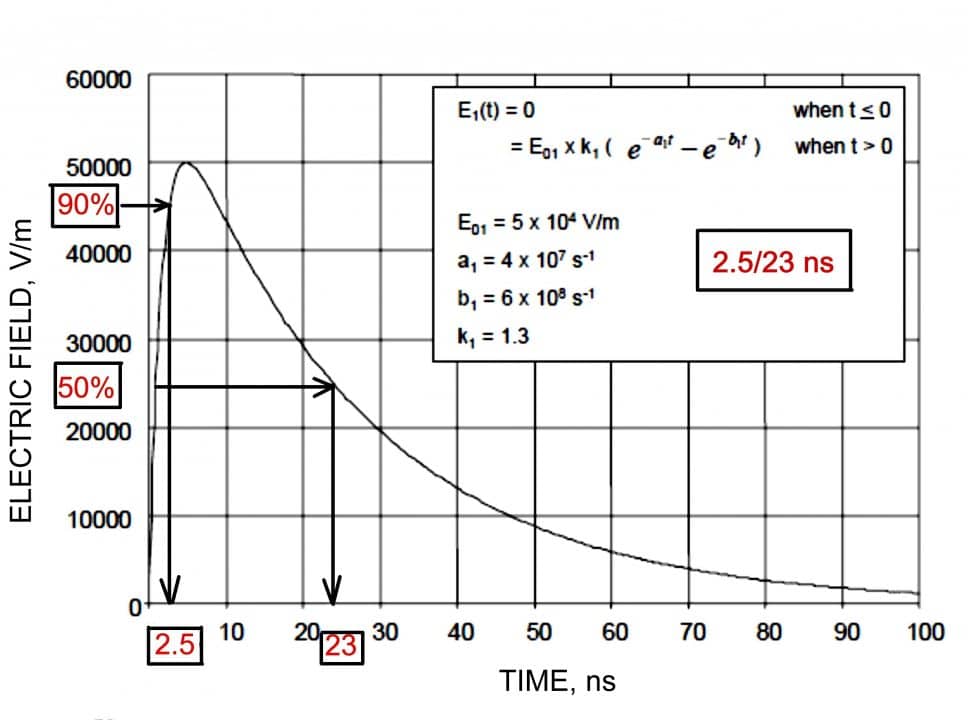
Figure 1: Standard shape of HEMP’s E1 pulse. - Instead of protecting specific types of employed electronic equipment, it is sometimes feasible to use back-up equipment of the same type stored in a shielded container directly at the facility being protected.
- Existing HEMP-simulating test benches provide inaccurate or insufficient information at immunity testing of power system’s electronic equipment, and thus testing such equipment (e.g. cabinets with electronic equipment) on such test-benches is not feasible.
3. Basic HEMP protection strategy for power system’s electronic equipment
The aforementioned provisions allow us to articulate the basics of the general strategy ensuring HEMP protection for power system’s electronic equipment.
- Due to technical and economic reasons, protection might only be provided to the most important (critical) types of electronic equipment installed at critical facilities of the power industry, rather than to all types of equipment employed at the power industry. Critical types may include equipment that is directly involved in electric energy generation and transmission, as well as main types of relay protection, control, and automation systems. Consequently, measuring systems, remote control, and remote signaling systems do not fit into this category of critical equipment.
- Protection of electronic equipment is multi-layered. The first (top) layer includes protected buildings and structures. The second layer includes protected rooms (halls) where equipment is installed. The third layer includes protected cabinets with electronic equipment. The fourth layer includes input and output terminals of the equipment itself. Some additional “layers” of protection may include devices preventing dangerous electromagnetic impacts on the input/output terminals of electronic equipment through the earthing system and electric cables (both control cables and power cables).
Each of the above-mentioned layers can be deployed with various levels of efficiency expressed as a percentage of its maximum efficiency. Specific situations at the power system facility may stipulate various modes of use: fewer layers with higher efficiency of each layer or otherwise more layers with lower efficiency of each layer. In each case the choice of protection layers should be based on the feasibility study of a specific situation. It should be noted that in case of existing equipment it is extremely difficult to use a single layer at 100% of its efficiency. However, a high level of the single layer’s efficiency can be achieved if a new project accommodates corresponding protection means.
Obviously, not all types of equipment installed in one building (e.g. substation building) should be considered as “critical.” Similarly, not all types of protection relays installed in one room (e.g. relay room) should be considered as “critical.” Thus, full protection of buildings and structures from EMP impact contradicts the above-mentioned principle No. 1. Using the first (top) layer of protection at a high-efficiency level will be economically viable for a newly designed substation only, as efficient protection of an existing building, which was designed without HEMP consideration, will be too difficult and economically unsound. Moreover, the new design can adopt corresponding architectural solutions as well as new building and finishing materials. It should be kept in mind that the shielding capability of building materials is very vague and inconsistent, thus its assessment can be very approximate (Figure 2).
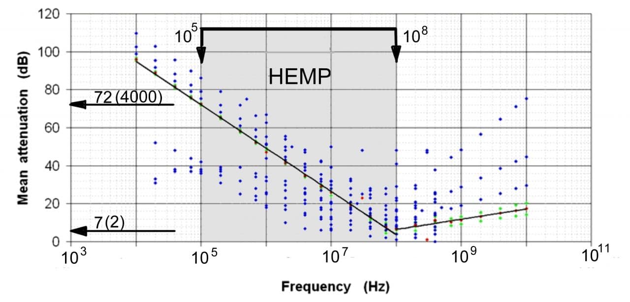
Figure 2 shows that attenuation introduced by the building can differ by 65 dB from the low to high region of the HEMP specific frequency range (105–108 Hz). Nevertheless, even ordinary construction materials, such as 30 cm thick cast reinforced concrete, which is used for construction of “protected” or “reinforced” rooms (according to the building standard, such room is now part of any new apartment in Israel) can significantly weaken electromagnetic emission. Despite the known specifications spread, it can be assumed that the walls made of cast reinforced concrete provide HEMP weakening by approximately 20 dB (i.e. by a factor of 10).
Feasibility of the second protection layer (at room level) depends on specific architectural and building conditions, which include complexity of the shielding of windows and doors, location of the room inside the premises, material, wall thickness, etc., as well as a proportion of critical equipment among all types of equipment installed in the specific room (hall). Despite the availability of diverse and efficient finishing shielding materials, e.g. varnishes, paints, plaster, fabrics, curtains, carpets, etc., their practicality for rooms in existing power facilities is questionable in terms of cost-effectiveness. On the other hand, it does not mean that they should be totally avoided, as they provide at least partial efficiency of this layer (i.e. for some weakening of electromagnetic emission entering this room). Concurrently, if it is possible to include a dedicated room for critical equipment into the construction design, this room can become one of the most economically and technically efficient protection of critical electronic equipment against the impact of HEMP.
The feasibility of the third “layer” of protection (dedicated protection cabinets) depends on availability of the second layer and its efficiency. When its efficiency is rather high, the third level may be avoided. In case it is not possible to use the second “layer,” the third “layer” must be used. Nevertheless, there are some options here as well. For instance, dedicated protection control cabinets, such as those offered by Schneider Electric (Figure 3), may be included in the design of a new substation.
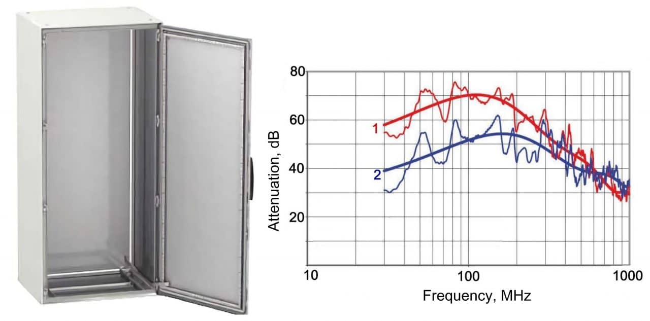
For existing power facilities (unlike the newly designed facilities) the third “layer” is often important and effective. Practical implementation of this “layer” through substitution of existing unprotected cabinets (often with glass doors, Figure 4) by special protected cabinets is unreal, and thus can be realized through upgrading of unprotected cabinets and their conversion into partially protected cabinets.

The fourth layer of protection is fundamental at almost any existing power facility, where the majority of control cables, current and voltage circuit cables and power supply cables are not shielded. This layer of protection is achieved by placing pulse voltage amplitude limiters (varistors and TVS-diodes) on input and output terminals of electronic equipment. It can be partially used (with lower efficiency) in new designs, provided all those cables are protected by multi-layered shields, which prevent HEMP pulse penetrating to the system.
3. One cabinet should, when possible, avoid critical and non-critical types of electronic equipment using shielded and non-shielded cables. When necessary, the working functions of critical equipment scattered around in different cabinets should be transferred to other types of equipment placed in a single cabinet to ensure protection of one critically important cabinet, (perhaps, several critically important cabinets) rather than all cabinets located at the power facility.
4. In some cases, it would be more efficient to use spare parts and equipment upon HEMP impact instead of performing complex activities to ensure protection of installed equipment. Considering the common chaos on the transportation system and failure of a communication system upon HEMP impact, generality of equipment damage at all power facilities simultaneously, and lack of staff to perform substitution, spare equipment must be stored in close vicinity to main equipment in enclosed shielding containers (Figure 5) in the ready-to-use state.

For example, in case of spare digital protection relays, they can be preliminarily tested and adjusted to necessary modes and feature corresponding actuation algorithms and settings.
Using spare equipment instead of protection elements and devices for installed equipment can be possible, provided:
- Cost of spare equipment is significantly less than expenses to ensure protection for installed equipment.
- Spare equipment can be prepared for commissioning in advance and commissioning itself will not require much time and extraordinary skills of employees; it can be performed by staff members who are not directly involved in the operation of this equipment based on the previously prepared instruction.
- Failure of employed unprotected equipment will not result in immediate cascade tripping of other pieces of equipment and interruption in generation and transmission of power, which require a significant amount of time for restoration.
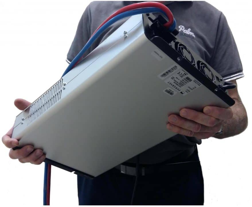
An example of equipment, which can be substituted by emergency equipment in case of damage, would be represented by the substation’s battery chargers that allow several hours for substitution upon emergency disconnection, provided they are equipped with a powerful battery. In addition to that, low prices and small dimensions of modern impulse power supplies involving a high-frequency stage, (Figure 6) (suitable for battery charging) combined with easy commissioning make them feasibly spare instead of complex protection of an employed charger.
Nevertheless, it should be kept in mind that in case of emergency, which will inevitably occur upon HEMP impact on a big area as well as during multiple simultaneous failures or emergency tripping of various electric equipment, substitution of emergency equipment may be impossible within the shortest possible time. Consequently, extreme care should be taken when considering using backup equipment instead of protection devices for employed equipment, even if backup equipment costs much less than protection means.
5. As a rule, HEMP resilience is tested on special HEMP simulating test benches and test sites. In fact, guided wave-type test benches (Figure 7), which are available in many countries, have been primarily developed for testing pieces of military equipment.
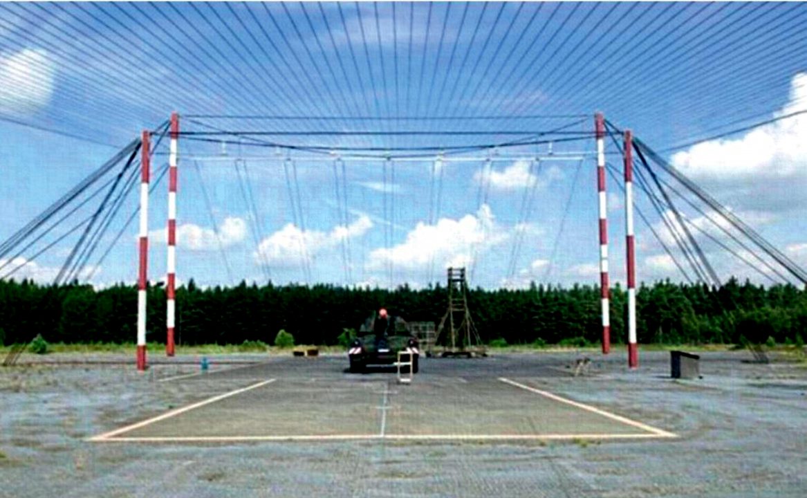
As shown in [3, 4] these test benches are of little help for testing cabinet-type equipment, which is used in the civil power industry and the results of these tests may be confusing or misleading. One of the reasons is that the designs and types of installed electronic equipment, as well as internal wiring layout of various cabinets with electronic devices, are different in terms of high-frequency specifications. Thus, the results of testing any individual cabinet for very short electromagnetic pulse impact cannot be extrapolated over other cabinets, i.e., in practice, there is no “typical” cabinet for such tests. Based on conclusions made in [3, 4], it is not feasible to conduct such tests for this type of equipment. The data presented in [1] regarding the resilience of computers and computer networks also confirm an extremely large scattering of test results, depending on the influence of a very large number of almost unpredictable factors and the inability to transfer the results of single tests of specific devices and systems to other devices and systems.
The general strategy should be based on maximum use of maximum amount of known protection means (selected based on the above-mentioned strategy) with restrictions to be determined by technical and economic capabilities of specific power system only.
This approach makes testing of device blocks on simulation test benches absolutely senseless, even if we forget about downsides of guided wave-type simulators. Nevertheless, some tests are necessary and important. They include testing of specific means (elements) selected for protection, such as varistors, filters, cabinets, cables, etc. The purpose of these tests is to check parameters declared by the manufacturer and to select the most efficient protection elements from the diversity offered in the market. These tests can be performed using generally accessible instruments manufactured by companies described in [1].
Specific protection means their specifications and application features have been previously addressed in [1].
4. Conclusions
The suggestions should help to ensure HEMP protection of critical pieces of electronic equipment will provide the staff of power facilities with a comprehensive impression on the problem and allow them to use the known methods and protection aids in a more efficient way.
References
[1] Gurevich V. Protecting Electrical Equipment: Good Practices for Preventing High Altitude Electromagnetic Pulse Impacts. – De Gruyter, Berlin, 2019. – 386 p.
[2] Gurevich V. Protection of Substation Critical Equipment Against Intentional Electromagnetic Threats. – Wiley, Chichester, 2017. – 228 p.
[3] Gurevich V. Testing HEMP Resilience of Electronic Equipment Used in Power Industry: Is It Essential? – International Journal of Research and Innovation in Applied Science, 2019, Vol. IV, Iss. V, pp. 115 – 118.
[4] Gurevich V. The Problems of Testing HEMP Resilience of Electronic Equipment of Automation, Control and Relay Protection. – International Journal of Research Studies in Electrical and Electronics Engineering, 2019, Vol. 5, Iss. 3, pp. 14 – 22.
