Introduction
NEBS was developed by Bell Labs in the 1970s to standardize equipment that would eventually be installed in a phone company’s central office (CO). Sorting out the acronyms, NEBS stands for “Network Equipment-Building System,” a term used to describe the environment of a typical Regional Bell Operating Company (RBOC). To get a basic understanding of NEBS, visit www.nebs-faq.com. This site contains helpful information on NEBS design, spatial and environmental criteria, maintenance, testing, and the checklists used by the Regional Bell Operating Companies (RBOCs). There’s also a handy heat release calculator to aid in designing for NEBS compliance. Using NEBS, a vendor can design telecom equipment that will be installed in a CO without disrupting operations–a decided plus in terms of economy and efficiency.
One of the many facets of this system is an electromagnetic compatibility (EMC) requirement. The specific document covering this area is Telcordia GR-1089-CORE, Electromagnetic Compatibility and Electrical Safety — Generic Criteria for Network Telecommunications Equipment. This document details EMC and safety criteria and applicable test methods. This article focuses primarily on the EMC criteria. A cautionary–but hardly complete–explanation of the NEBS Fire Resistance test also is included as well.
GR-1089-CORE breaks the criteria down into several sections. Electrostatic discharge (ESD) and EMI are included. Radiated emissions (electric and magnetic fields) are included along with conducted emissions such as AC power leads, AC and DC power and signal leads, and analog voiceband leads. Other sources of interference or problems detailed are lightning and AC power fault, steady-state power induction, and DC potential difference. The final vital considerations are electrical safety, bonding and grounding, and corrosion.
GR-1089-CORE and FCC Part 15
Ordinarily, compliance engineers turn to the Federal Communication’s Commissions Rule 15 for guidance on EMC testing. Actually, one part of that rule FCC 47 CFR 15.103, 15.103(b), specifically exempts public utilities (RBOCs and Interexchange Carriers (IXCs).
GR-1089-CORE imposes stricter requirements on network equipment than the FCC and requires compliance from 10 kHz to 10 GHz. This standard differs from the FCC requirement to test to multiples of the highest clock frequency. In fact, the FCC limits could be considered a less exacting subset of the GR-1089-CORE limits. Still, with good EMC design practice, the GR-1089-CORE range should not be a problem–at least the limits are Class A in a CO.
The exemption from the FCC rule is provided with the understanding that if a piece of network equipment causes interference, “The operator of the exempted device shall be required to stop operating the device…” This exemption gives the service provider a great deal of flexibility in putting network equipment into service. Ceasing to operate would be unacceptable for call-processing equipment, so the service providers police themselves. This requirement doesn’t mean that each installed piece of network equipment complies with the GR-1089-CORE limits. A few frequencies might be over the limits as long as there is no harmful interference. Note that the exemption applies to “equipment …in a dedicated building…” The equipment is under the control of the service provider with a very real economic incentive to provide reliable phone service.
EMC Design
Good EMC design practice should be used throughout product development. There are many excellent texts on this subject. Several factors are crucial to effective EMC design including:
- Component placement.
- Multi-layer board stack up definition.
- Early and on-going EMC design reviews.
- Hooks provided for signal line filtering.
- Enclosure shielding considered from the beginning–with cooling and fire resistance factored in.
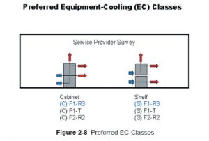
In reference to the final factor, the optimal NEBS cooling design has air coming in from the front and exiting from the rear or top (Figure 1). Deviations from this practice may lead to the rejection of equipment by an RBOC. It also helps to have each board reviewed multiple times by an EMC rule-based application.

The Hierarchy of Testing
It can be disastrous to jump right into final EMC testing. Testing should be performed early and often. This point cannot be overemphasized; early testing saves time and money. Some testing can be performed in-house, but it may be cost-effective to perform other testing at a qualified EMC lab.
Testing for Fire Resistance
Flames and charred equipment would seem to be a much more blatant problem than EMI, as well as a problem beyond the purview of EMI testing. The crucial fact is that the fire resistance test must be carried out before attempting EMC testing. Many products fail this test, and flame retardant measures should be taken as early as possible in the design process.
What is the NEBS Fire Resistance test? The Telcordia standard, GR-63-CORE, requires that a product be set on fire from the inside. A methane line burner (Figure 2) is inserted into the product and allowed to burn for 5 1/2 minutes. All nearby flammable material is ignited. Often, a product is completely destroyed. No simulations or predictions are acceptable. The product must be set afire and the results assessed.

Electrostatic Discharge (ESD)
Similarly, there is much value in performing early ESD testing. If system software is not available (and it usually isn’t), diagnostic software can be used. A working alliance between the software and compliance engineering teams can prove invaluable.
EMC Compliance and Susceptibility
Since any changes late in the design cycle can have a considerable impact on EMC, testing throughout the design process is vital. Even early prototypes of diagnostic software can yield valuable emissions data. An early scan, preferably in a 10-meter chamber, can show weak elements of the EMC design. A quick test for shielding effectiveness can be performed by inserting a portable comb generator inside the empty chassis. This information can be factored into the next board spin, improving future test results.
Conducted Emissions
Conducted emission testing can be performed right after radiated emission testing. The conducted emissions test is relatively simple with proper test equipment. This equipment is generally available at the same lab used for EMI testing.
Lightning and AC Power Fault
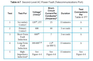
It is cost-effective to get the destructive Lightning and AC Power Fault tests out of the way as soon as possible. It is very difficult to predict how a board will react to 600 V at 60 A for five seconds until such an eventuality occurs. Remember that the test with the highest energy may not be the worst case. It could be a voltage and current that lies between the maximum and minimum energy (Figure 3). Also, any damaged board from the fire resistance test can be used in this test. (In fact, some manufacturing and engineering teams hold all defective boards for destructive testing.) In the event of failure, design changes can be made, and product development can proceed.

Bonding and Grounding
There are some short circuit tests in this area that can be performed early. All power sources are shorted individually. This can be performed in-house in a lab environment.
Conclusion
A careful design plan and testing throughout the design process simplifies product development. They help to assure that equipment will comply with the limits of GR-1089 CORE and will find a place in a CO, thus assuring the reliability of the telecom infrastructure.
Addendum
Section 15.103 Exempted devices.
The following devices are subject only to the general conditions of operation n Sections 15.5 and 15.29 and are exempt from the specific technical standards and other requirements contained in this Part. The operator of the exempted device shall be required to stop operating the device upon a finding by the Commission or its representative that the device is causing harmful interference. Operation shall not resume until the condition causing the harmful interference has been corrected. Although not mandatory, it is strongly recommended that the manufacturer of an exempted device endeavor to have the device meet the specific technical standards in this Part.15.103(b). A digital device used exclusively as an electronic control or power system utilized by a public utility or in an industrial plant. The term public utility includes equipment only to the extent that it is in a dedicated building or large room owned or leased by the utility and does not extend to equipment installed in a subscriber’s facility.
Bibliography
Telcordia GR-63-CORE, Issue 2, April 2002. NEBSTM Requirements: Physical Protection.Telcordia GR-1089-CORE, Issue 3, October 2002. Electromagnetic Compatibility and Electrical Safety–Generic Criteria for Network Telecommunications Equipment.Telcordia GR-3028-CORE, Issue 1, December 2001. Thermal Management In Telecommunications Central Offices: Thermal GR-3028.Dave Lorusso. “NEBS 101: Introduction to NEBS,” Compliance Engineering Magazine, March/April 2003.Dave Lorusso, “NEBS Certification–Design With The Customer in Mind,” Conformity, October 2002.Part 15 of the FCC Rules, 47 CFR 15.
Resources
www.nebs-faq.com: Resource for NEBS Compliance information.www.creepage.com: (Creepage and clearance calculators).www.verizonnebs.com – Verizon’s NEBS Compliance Web Page.www.telcordia.com: The creator and keeper of NEBS documents.www.lorusso.com: Lorusso Technologies, LLC, “Your NEBS, Product Safety and EMC Solution.”
DAVE LORUSSO is a specialist in NEBS design and testing. He can be reached by phone at 512-695-5871, or by email at dave@lorusso.com.
