Sulekh Chand and Nurul Hasan
Electronics Regional Test Laboratory (North), New Dehli, India
As computer usage increases, stable sources of AC power are a must. The computer needs a continuous 220 V AC source for its operation. In many parts of the world, the public utility supply is not stable, and disturbances and interruptions in power are frequent. To avert possible data loss, computer systems need uninterruptible power supplies (UPS).
An uninterruptible power supply provides a stable power supply to the system in the presence/absence of the input supply and uses an inverter to convert DC to AC power. This inverter can generate unwanted electromagnetic interference (EMI) and also can be susceptible to EMI generated by nearby electrical equipment.
Principle
The UPS is an electronic power system whose prime function is to provide specified continuity and quality of power in the event of any partial or total power failure of the normal source of power. This is accomplished by conveting some form of stored energy to supply power for a specified period of time when the public utility power is no longer available or within acceptable limits. There are two types of UPS, the on-line Ups and the off-line UPS.
On-line UPS
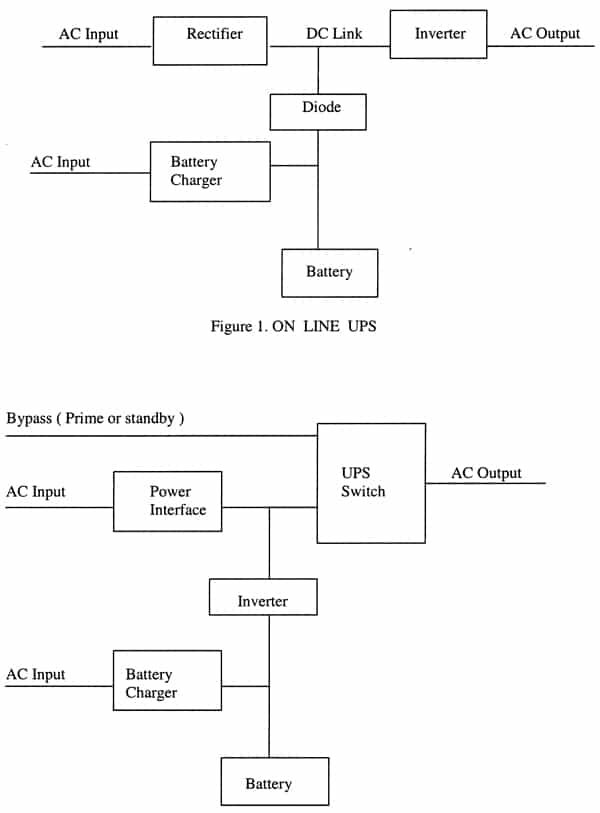
The on-line UPS supplies output power through the inverter regardless of the condition of the AC input supply. A block diagram of an on-line UPS is shown in Figure 1. Usually, the AC energy is rectified and stored in a battery bank. The stored DC current is then converted back to the supply mains (the output of the UPS) via the inverter. When the AC input is not available or is beyond UPS tolerances, the unit enters the stored energy mode of operation, where the battery/inverter combination continues to support the load for the duration of the stored energy time or until the AC input supply returns to normal. In the event of a rectifier/inverter failure or load current becoming excessive, either transiently or continuously, the unit enters a bypass mode where the load is temporarily supplied via the bypass line from the primary or standby power source.
Off-line UPS
An off-line UPS is one that supplies the power to the load by an inverter/battery combination in the absence of input power. A block diagram of an off-line UPS is shown in Figure 2. In a normal mode of operation, the output voltage is supplied with conditioned AC input. When the AC power supply is either not available or unacceptable. The unit runs in stored energy mode for the duration of stored energy time using a battery backup until the AC input supply is restored, In the event of UPS failure, the lode may be transferred to bypass mode.
EMI/EMC Evaluation
The UPS uses an inverter to convert DC voltage into AC voltage to maintain the quality and continuity of the AC voltage supply. Inverters are made with technologies that are normally sensitive to EMI disturbances and also act as a source of EM pollution. EMC evaluations of these UPSs are required essentially to determine their electromagnetic compatibility with their surrounding environment. Testing is performed per various national/international standards. During testing the UPS is loaded to rated capacity.
Typical Applicable Specifications
The following specifications are typically used for testing uninterruptible power supplies.
- IEC 62040-2, (1999-02) Uninterruptible Power Systems (UPS) – Part 2: Electromagnetic Compatibility (EMC) requirements and EN 50091-2: 1996, Uninterruptible Power Systems (UPS) – Part 2: EMC requirements
- IEC 62040-3, (31-Mar-1999) Uninterruptible power systems (UPS) – Part 3: Method of specifying the performance and test requirements and EN 50091-3, Uninterruptible Power Systems (UPS), Part 3: Performance requirements and test methods.
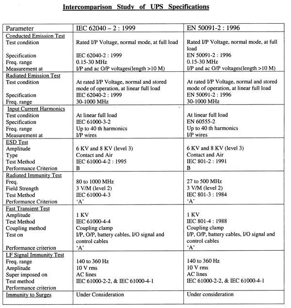
A comparison of the requirements of the standards is shown in Table 1.
EMC Evaluation
Before conducting EMC testing, a performance test plan is prepared per the UPS manufacturer’s specifications to verify UPS performance when it is subjected to various electromagnetic environments. Crucial performance parameters are selected to evaluate the UPS per IEC 62040-3. The testing is conducted in normal mode and stored mode. The UPS is evaluated per the following parameters.
- Conducted emissions on the input and output lines
- Radiated emissions
- Current harmonic test
- Electrostatic discharge (ESD) test
- Electrical fast transient test
- Radiated immunity test
- Low frequency immunity test
EMI/EMC ANALYSIS AND COMPLIANCE PRACTICES
Conducted Emissions Testing
The conducted emission measurements are made using a LISN or probe to capture the noise present in the power line of the equipment between 150 kHz and 30 MHz. Since the UPS may be used in either an industrial or domestic environment, the relevant criteria for compliance must be checked.
Common sources of conducted emissions are the inverter and the charging and processing circuits. The emissions increase due to placement of components, the merging of wiring routes, improper filtering and faulty grounding. Generally, compliance can be achieved by appropriate filtering at the input supply, the proper grounding connection, planned wire harnesses, and the placement of ferrite beads on switching components.
Radiated Emissions Testing
Radiated emissions measurements are performed in the 30 to 1,000 MHz frequency range. The main sources of radiated emissions are the switching frequency layout and wiring and ventilation holes. Compliance can be achieved with proper filtering at the input and output lines, grounding, component layout and good cabinet design.
Current Harmonic Testing
Solid-state electronics offer several design advantages for the UPS inverter and processing circuits. The UPS uses thyristors, triacs, switching transisters and field effect transistors (FET) to convert the DC to the AC power supply. This causes considerable mains pollution in the form of waveform and amplitude disturbances.
If switching does not coincide with crossing of the mains waveform, it can introduce distortion into the mains supply. Current harmonics can cause a voltage drop.This will lead to reduced efficiency of all the connected devices. Asymmetrical phase control; generates both odd and even harmonics as well as a DC component. This can lead to saturation of mains transformer. Other effects of harmonics are excessive heating of the conductor, false tripping of the circuit breakers, distorted voltage, increase in hysteresis, and eddy current loss. Compliance can be achieved by using a coil at the end of the rectifier and before the filter capacitors, so that the fluctuation in the current can be smoothed. Hence, reduction in the current harmonics. Other methods of harmonics suppression techniques are also used including passive and active filters.
Filters
Passive filters are mainly used to suppress the amplitude of one or more fixed frequency currents/voltages. A series filter shunt filter or combination of the two may be used. The series filter is used to prevent a particular frequency from entering selected circuits. This type of filter offers high impedance to the relevant frequencies. Shunt filters provide a shunt path of low impedance to harmonic frequencies.
Harmonics can be eliminated by magnetic flux compensation. A current transformer is used to detect the harmonic components from the non-linear load and these are fed through an amplifier into the tertiary winding of the transformer in such a way that the harmonic currents are cancelled.
Using offsetting harmonics to cancel unwanted harmonics is another method of suppression. An active filter senses the voltage and current harmonics and generates off-setting harmonics to cancel the unwanted harmonics. High frequency PWM drives are used to generate off-setting harmonics. An active filter gives a clean waveform to the load.
ESD Testing
Immunity against electrostatic discharge is usually checked by applying a 6 kV contact and 8kV air discharge pulses per the requirements of the applicable standard. Non-compliances are observed mainly due to improper grounding of systems and improper placement of components. Compliance can be achieved by using tight cabinet joints, proper grounding connections, reducing ventilation holes to the smallest feasible diameter. The UPS interface connected to the computer is mainly connected and must be protected.
Electrical Fast Transient Testing
This test is usually performed for EFT noise of 1 kV. During the presence of EFT noises in the input supply, the input/output shall be within the specified limit of the UPS specifications. EFT pulses can affect the digital signal. Digital sensitive circuits are used in the UPS for display purposes and for control interface for switching on/off the system using computer. Moreover, it can also affect the performance of the UPS. Compliance can be achieved by using a decoupling circuit at the input/output of DC supply for digital sensitive circuitry. Improvement can be achieved by separating mains and sensitive circuitry and by using ferrite beads at the input/output of the UPS system.
Radiated Immunity Testing
During this test, the UPS is subjected to an RF field of field strength 10 V/m in the frequency range of 27 to 500 MHz (80 t0 1000 MHz) to verify the immunity against radiated noises. The RF noise can enter the UPS through the input, the output and the DC supply connecting leads and can penetrate through ventilation holes. There is usually a filter at the input and at the output filters are not conventionally used. Since input and output leads are lengthy, they can pick up RF signals and carry them into the system. Compliance can be achieved by using a filter at the output connecting leads and by proper cabinet and shielding design.
Low Frequency Immunity Testing
The function of the low frequency immunity test is to check system immunity to low frequency noises present in the power supply due to generation of harmonic noises by any system in the vicinity. The test is usually performed between 140 Hz and 360 Hz for 10rms amplitude superimposed on the AC supply. This can create a short, quasi-instantaneous effect which may range from an occasional malfuction to the damage of electronic components and a long-term effect may lead to excessive heating of the connecting wires and components. Noncompliance occurs as a result of a poorly filtered input circuit. A filter coil for suppressing low frequency noise can be used for compliance. The coil smoothes the supply and the UPS provides the desired output.
Surge Testing
This test is performed to check the immunity against surges present on the power line due to lightning and switching of heavy inductive loads. Surge test level is under consideration according to specification. However, this test is usually performed at 2 kV and 4 kV for differential and common mode respectively. Non-compliance occurs due to poor insulation of internal wiring, low creepage distances and the absence of surge protectors (e.g., MOVs). Properly insulating the internal wiring, adequate creepage distances and the use of MOVs help to achieve compliance.
Evaluation in Context of Working Environment
Presently specifications available for testing UPS systems are getting out of pace due to fast technological growth. The EFT test usually performed by the capacitive clamp method needs to be reviewed. Since the UPS input supply is taken directly from the the public utility power system which has various types of noises, the effect on the performance of the UPS may be measured using direct coupling rather than capacitive clamp method. As per the specifications, the surge test is under consideration and optional. Surge testing should be mandatory. Voltage dip/interruption test shall also be included in the specifications.
CONCLUSION
Probable causes of EMI noise have been discussed. Techniques for noise suppression and immunity improvement that could be incorporated into the UPS at the design stage have been reviewed.


