EMC testing is an unavoidable part of the development cycle for electronic products. As clock frequencies continue to increase, radiated emissions get harder to control. In an ideal world, the R&D engineer would test the emissions from his product early in the design stage and retest frequently as design changes were made, just ass he tests whether his product meets its other design requirements.
Unfortunately, practical constraints make this difficult. Regulatory requirements dictate that radiated emissions be tested at open sites or in shielded rooms. Most companies don’t have the equipment to do this testing, and subcontract it to outside test houses. Even if a company has its own test facilities, these may be booked well in advance, making testing difficult. Either way, the end result is that EMC testing frequently is not done until late in the project development cycle. As a result, designers do not discover EMC failures until late in the development cycle, when schedule pressures are at their highest.
THE TEST-TWEAK CYCLE
When a product fails EMC testing, the design engineer brings the product back to the lab and tries to isolate the source of the problem. Using measurements, rules of thumb, and intuition, he makes modifications to the design. These changes might include adding shielding to problem circuits, adding filtering to I/O lines, or other modifications.
The product is then returned to the EMC test site, and the tests are repeated. If the product fails, this cycle is repeated again, as many times as necessary:
 Each iteration through the loop delays product shipment, costs money, and adds to frustration.
To break this loop, we need to be able to do two things: To make radiated emissions measurements on the bench, and to be able to establish correlation between measurements in the lab and measurements at the test site.
ESTABLISHING LAB-TEST SITE CORRELATION
The lab engineer can measure emissions from his product in the R&D lab using handheld EMC probes. The ideal probes have the following characteristics:
- Handheld
- Repeatable
- Compact
- Flexible
- Wide frequency response
- Sensitive to magnetic or electric fields
The probes in the Beehive Electronics 101A EMC probe set have all these characteristics. Unlike homebrew probes, their sensitivity is known and specified. The “The Test-Tweak Cycle” probe set contains both magnetic- and electric-field probes, with individual probes optimized for different frequency ranges. Since the probes use push-on SMB connectors, cables won’t kink when twisting the probes to reach tight corners.
With repeatable probes, it is possible to establish correlation between measurements on the lab bench and measurements at the EMC test site. The lab bench and test site readings will then be related by a simple frequency-dependent offset. Although it is difficult to predict this offset in advance, it is easy to calculate it in practice with data from both locations.
AN EXAMPLE OF SUCCESSFUL TROUBLESHOOTING
The following example shows how these principles have been successfully used in practice to solve EMC problems by one of the authors.
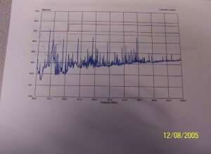
The product in question underwent radiated emissions testing to CISPR 11 specifications. After testing in the semi-anechoic room (Figure 1), the device under test (DUT) failed the specification at a frequency of 100 MHz (Figure 2, 100 MHz peak marked with red arrow).
In the graph of Figure 2, the dashed red line represent the pass-fail limit for testing in this particular semi-anechoic room. The 100 MHz emissions were approximately 22 dB beyond the specification limit. This was an alarming problem. Experience suggests that it is very difficult to improve emissions by over 20 dB without significant design changes.

A problem of this magnitude will usually require several design changes to improve the emissions enough to meet the specification. The typical approach would be to make a number of design changes to improve the emissions. After each change, the DUT would be returned to the semi-anechoic room and radiated emissions testing would be repeated. This process is both time-consuming and expensive. In this case, the project schedule would not allow the weeks that might be required to solve the problem.

For this reason, it was necessary to take a different approach. Rather than evaluating each design change in the semi-anechoic room, each design change would be evaluated on the benchtop in the R&D lab using a small magnetic field loop probe. The improvement in radiated emissions would be measured for each design change. Only when lab measurements showed that the improvements were sufficient to enable the DUT to pass spec would the DUT be returned to the semi-anechoic room for additional (and hopefully final) testing. If the correlation between benchtop and test site measurements was good enough, only one more pass through the semi-anechoic room would be necessary.
Back in the lab, the first step was to identify the source of the emissions. A small magnetic field loop probe was used to find the location of the strongest 100 MHz emissions. The source was quickly identified as the DUT’s LAN cable.
Next, the DUT’s cover was then removed and further probing was done inside the box. Using the probe, it was easy to identify the source of the emissions. The 100 MHz emission was the 5th harmonic of the 20 MHz microprocessor clock in the system. This was coupling into the LAN circuitry and, from there, coupled onto the LAN cable.

With the source of the problem identified, the next step was to use the probe to evaluate the effectiveness of design changes. When ‘sniffing’ for radiated emissions, repeatability will be improved if the probe location is held constant. For this reason, the probe was attached directly to the LAN cable with cable ties (Figure 3). The probe output was monitored on a spectrum analyzer.
The spectrum analyzer was tuned to a center frequency of 100 MHz, and the level of radiated emissions was read using the spectrum analyzer’s markers. Several changes to the design were made. After each design change, the level of the 100 MHz emission was recorded.
Three changes were identified that made significant improvements in the level of radiated emissions:
- Ferrites were added to the transmit and receive lines between the LAN transformer module and the RJ45 connector.
- The LAN transformer was changed to a model with a built-in EMI suppressor.
- The LAN cable that ships with the product was changed to one that had a ferrite core around it. Although this was effective, it raises difficult issues. Even if the product is shipped with the special LAN cable, there’s nothing to prevent the customer from using an ordinary cable in the field.

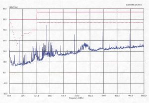
Benchtop measurements predicted that the first two modifications, taken together, would reduce emissions by the required 22 dB. The third fix, changing the LAN cable, should not be necessary. The DUT was returned to the screen room with the first two changes, and the CISPR 11 test was repeated. The results are shown in Figure 4.
As can be seen from the graph, emissions at 100 MHz were reduced enough to meet the CISPR 11 specification. Despite the fact that over 20 dB improvement in 100 MHz emissions was needed, the first test of those improvements resulted in success. Because radiated emissions could be measured effectively on the lab bench, the test-tweak cycle had been broken.
Terry Noe has worked for 25 years in the fields of EMC, RF, and analog design. He is president of Beehive Electronics, which produces a line of EMC test equipment. He also provides consulting and custom design services in the fields of EMC, RF electronics, and transceiver design. He received a BSEE from Virginia Tech in 1985 and a MSEE from Stanford University in 1989.
Udom Vanich received a bachelor’s degree in Electrical Engineering from San Jose State University and a master’s degree in Electrical Engineering from Colorado State University in 1987. He was co-founder of Pacifica International, LLC from 2003 to 2006. He is currently an RF application engineer for CSR.
