In the last article of critical DO-160 sections we talked about pin injection testing for indirect lightning. Like pin injection, cable bundle is under Section 22.0 of DO-160. However, cable bundle is a completely different beast and warrants its own discussion.
For future articles we will also be discussing the following sections of DO-160 so stay tuned for more great discussions on these critical sections.
Critical sections DO-160
Sect 16.0 – Power Input
Sect 20.0 – Radio Frequency Susceptibility (Radiated and Conducted)
Sect 21.0 – Emission of Radio Frequency Energy
Sect 22.0 – Lightning Induced Transient Susceptibility (Pin Injection and Cable Bundle)
Indirect Lightning
As discussed before, indirect lightning simulates the coupling of energy onto a products cables during a lightning strike. DO-160 separates testing of Section 22 into three sections; pin injection, single/multiple stroke, and multiple burst.
In this article we will focus on cable bundle testing which includes single/multiple stroke and multiple burst. An example of a DO-160 requirement is shown below. The “G4L3” is the part of the requirement that relates to cable bundle testing.

Figure 1: DO-160 Section 22.0 Category Explanation
The letters in the requirement give the waveforms that will be tested whereas the numbers give the test levels. Different letters are assigned based on your aircraft environment. In section 22.3.1 an explanation is given to which waveform sets apply to which environments.
For example, waveform sets A, C, E, G and J are applicable to equipment with interconnecting wiring installed in locations of airframes that are metal. Whereas waveform sets B, D, F, H and K are applicable to sections of the airframe that may have structural resistance such as carbon fiber composite structures.
Carbon fiber composite structures cannot carry the current of a lightning strike as efficiently as metal. The induced waveforms on the cable is typically at a higher level and a longer duration. As a result, waveforms 4 and 5A are added to these waveform sets.
Additionally, the tests and waveform sets are also separated by cables that are shielded versus unshielded. This further divides the grouping. Test waveforms E, F, J and K are applicable to interconnected wiring that is shielded. Cable bundle waveform sets C, D, G and H are applicable to unshielded wire bundles.
Thus, a natural grouping can be established as shown in Figure 2.

Figure 2: DO-160 Section 22.0 Waveform Set Groupings
Cable Bundle – Single/Multiple Stroke
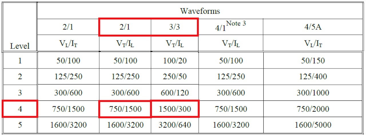
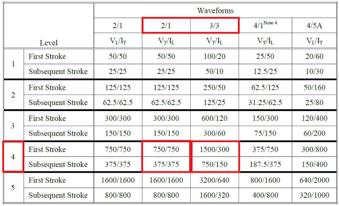
As seen in the example in Figure 1, cable bundle single/multiple stroke has a requirement of G4. The letter G indicates the waveform set and the number 4 indicates the test level. In figure 3 below, we can see that waveform set G requires the test waveforms 2 and 3. Looking at the test levels in figures 4 and 5 we can then trace to the level 4 requirement. This is indicated in red below.

Figure 3: Cable Bundle Test Requirements

Figure 4: Test and Limit Levels for Cable Bundles Single Stroke Tests

Figure 5: Test and Limit Levels for Cable Bundle Multiple Stroke Tests
VT indicates a test level that should be achieved by monitoring the voltage. IL indicates a test limit that should be achieved by monitoring current. The reason this test is looking for voltage as primary measurement is because the cable bundle is considered to be unshielded. Unshielded cable bundles are expected to hit a voltage level whereas shielded cable bundles are expected to hit a current level. This is due to the fact that shielded cables will conduct the injected transient down the shield in a low resistance path.
It should be noted that in multiple stroke the first test stroke is the highest followed by 13 additional strokes at a lower level.
Simulations should be done to ensure that your protection devices can handle these high surges. Additionally, simulations can and will show the overvoltage stress that may occur in downstream circuitry.
AerospacePal has free simulation tools with prebuilt waveforms as shown in figure 6. This also includes hundreds of TVS models already linked to make simulation and circuit analysis easy. You can check out all that AerospacePal has for indirect lightning simulation by checking out AerospacePal’s toolbox.

Figure 6: AerospacePal’s prebuilt DO-160 Lightning Waveforms
An example of your test environment can easily be constructed using these waveforms. Figure 7 shows one such example of using WF3 induced onto and equipment’s pin.

Figure 7: AerospacePal LTspice Example of WF3 Applied to One Line of an EUT
Cable Bundle – Multiple Burst
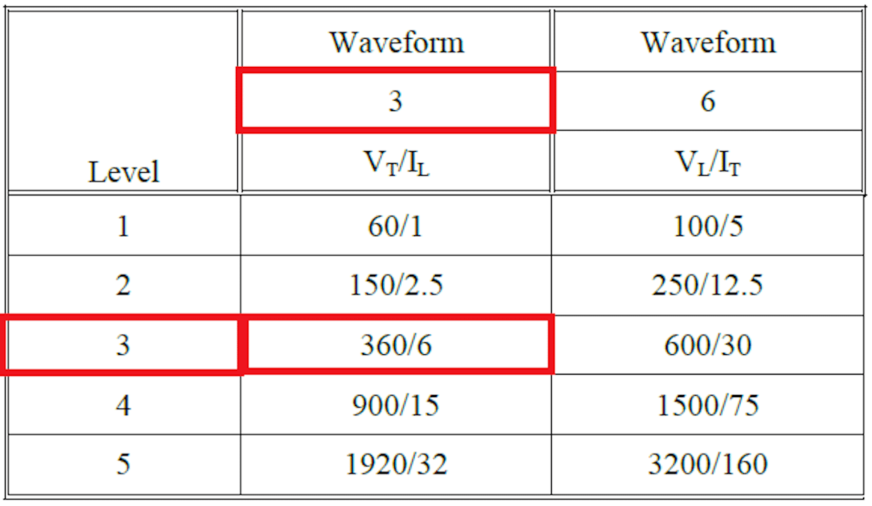
Much like multiple stroke, multiple burst injects a series of pulses onto your interconnecting cable bundle. Going back to the example requirement in figure 1, we see a requirement of L3. As shown below in figure 8 that translates to the following.

Figure 8: Test Levels for Cable Bundle Multiple Burst Tests
Though multiple burst is notably less severe in voltage and current than single stroke, it is applied many times in the course of less than one second. This cumulative energy can stress components just the same. However, if you’re testing to long-duration waveforms like waveform 5a, it is likely less total energy.
Multiple burst can also cause failures that might not be seen by less frequent transients like single stroke. When applying the 60 transients in a somewhat random time duration, it is more likely that a transient happens during what might be a critical moment for hardware or software. As seen in figure 9, the 60 transients are applied in a given range of time.

Figure 9: Multiple Burst Application
Acceptance Criteria
The acceptance criteria for cable bundle testing (single stroke, multiple stroke, multiple burst) is typically different from that of pin injection testing. As mentioned in my previous article, pin injection testing is a damage tolerance test meaning the unit under test does not need to function during the test. Rather, the unit is only expected to function after the test (and after a potential power cycle).
In contrast, most units during cable bundle testing have the expectation that the unit will function before during and after the test. That means that if a fault occurs during the test the unit fails the test. This can be particularly challenging for sensitive circuits that will have coupled energy from the test lightning strike.
This increased vulnerability makes it that much more important to simulate the effects of this transient on your unit.
DO-160 Cable Bundle Summary
DO-160 lightning induced transient susceptibility or indirect lightning is typically the most severe transient test in all of DO-160. From a damage tolerance perspective, pin injection testing (as discussed in my previous article) is typically worst-case because many products have shielding or in over braid that takes the majority of the lightning pulse during cable bundle testing. However, cable bundle testing requires the unit to operate through the lightning strike making the unit more susceptible to failure.
Thus, simulation of these circuits and the lightning strike applied should be done prior to spending top dollar at a professional testing house at Qualification. As discussed above you can use the tools provided by AerospacePal.com to quickly and effectively simulate your requirement and your circuit.
Next time you go to test DO-160 indirect lightning, have the confidence that your unit will pass by doing your homework beforehand. Reach out to me at patrick@aerospacepal.com if you have any questions.


