Test standards are running behind the fast pace of technological change.
Nicholas Wright
EMC-Partner, Laufen, Switzerland
INTRODUCTION


Escalating costs and increasing complexity in modern aircraft has ensured that aircraft design and assembly is now a global phenomena. Today, subsystems can be designed, manufactured, and tested at any location around the world, then shipped to the final assembly plant on demand. This global process requires that testing produces identical results no matter where in the world it is performed. Standardization of test methods and equipment go a long way toward achieving this objective. In terms of lightning testing, civilian aircraft and systems use the DO-160 standard which is ideally suited to fulfil the standardization role and is used as the basis for airworthiness certification.
Two sections of DO-160 deal with lightning effects, and there is a close relationship between them.
- Section 22 (Lightning induced transient susceptibility)
- Section 23 (Lightning direct effects).
Section 22 specifies requirements for equipment level tests using indirect lightning effects; section 23 deals with direct lightning strikes on airframes. Section 22 is more applicable to the global nature of aircraft system and equipment production. It is limited to tests on LRUs (Line Replaceable Units) and their interconnection cables.
The direct lightning effects testing covered by section 23 of DO-160 is performed on whole aircraft, usually in only a few locations (aircraft manufacturers) and therefore has very specific space requirements. The external or direct lightning event is characterized by high current discharges reaching 200 kA and is described as a “four component” test, as there are four distinct phases to the lightning event.
The generation of such discharges requires large and very expensive test equipment and a lot of space. This type of testing is certainly more representative of the real event, but it poses additional problems in evaluating the effects and assessing any latent damage that may have occurred to equipment, cabling or interfaces. This task may take many years to complete and can be significantly more expensive than the test itself.
In the field of military aviation, there are many standards in use at national levels: DEF-STAN 59-41 in the UK, GAM-EG13D in France, JDS-NDS0011B in Japan, and a multitude of MIL-STDs from the USA. There are no global standards covering military testing although the STANAG documents provide a degree of integration amongst NATO member states.
MIL-STD-461E specifies a series of tests at LRU level that give a good basis for immunity before the equipment is integrated into a system. Tests on complete platforms are dealt with by MIL-STD-464 which is parallel to the DO-160, section 23 tests.
Joint projects are not new in either the civilian or military world but they still provide an interesting situation where national standards are no longer entirely applicable, and a consensus must be reached between participating nations as to which tests must be performed.
One example is the Eurofighter Typhoon developed jointly by the UK, Germany, Italy and Spain. This aircraft has its own unique set of test requirements incorporated into SPE-J-000-E-1000, drawn from a variety of sources and adapted for the particular application.
Another example is the NH90 helicopter program, a joint venture between Eurocopter (France & Germany), Augusta (Italy) and Fokker (Netherlands). As part of the NH90 test program, lightning test requirements are based on the FAA AC20-136 which is equivalent to DO-160 with some modifications appropriate to the airframe and its operating environment.
Finally, the largest such project currently being pursued is the Joint Strike Fighter (JSF) or F35 with the US and UK as the main principals, and with Italy, Netherlands, Turkey, Canada, Australia, Denmark and Norway as partners. Latest indications are that the lightning test requirements for the JSF program may be based on both MIL-STD-461 and DO-160 requirements.
For sure, most of the changes taking place are being driven by technology. The increasing use of non-metallic materials in the airframe and the increasing use of high speed sophisticated processors and control buses play a significant role in which direction future standards will develop.
BACKGROUND
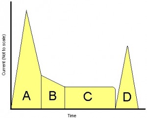
The external lightning environment can be simplified into four waveform components—A, B, C and D. These waveform components interact with an aircraft’s structure to induce voltage and current transients on the internal cabling and equipment.
Component A represents the initial stroke of a lightning event with amplitudes up to several hundred kiloamps. This component carries the highest energy level. Component B is an intermediate current of some tens of kiloamps which reduce to component C. Component C represents current flowing in the lightning channel. This flow can last for some milliseconds with currents in the hundreds of amperes range. Component D corresponds to restrikes on the airframe with peak amplitudes in the tens of kiloamp range.
There are several mechanisms by which the external lightning event is coupled into an aircraft’s systems. In reality, most transients are induced as complex waves through several coupling paths. For practical purposes, these paths can be narrowed down to two basic mechanisms: resistive coupling and aperture coupling.
Resistive Coupling
This mechanism produces voltages in the loops existing between cables and an aircraft structure. If the structure is highly conductive, the voltages may have the waveshape associated with the external environment. Because of this, the most common transient voltage is that associated with component A. This translates to the Waveform 4 definition (6.4/70 µs). This waveform can also be present in cable shields derived from the shield current and transfer impedance.
Low resistance cables, connected at both ends to the airframe structure will be subjected to a current transient derived from the external lightning event, galvanically coupled between the low inductance airframe and the relatively high inductance cables. An aluminium airframe presents a low impedance path so the transients will be long but relatively low in amplitude. Structures comprised of composite material give rise to shorter transients with higher amplitudes.
These different transfer characteristics have resulted in two waveforms being employed. Waveform 5A (40/120 µs) models resistive coupling through a composite structure. Waveform 5B (50/500 µs) models resistive coupling through an aluminum structure.
Aperture Coupling
Nowadays, the aircraft structure is not homogeneous; both Boeing and Airbus have been steadily increasing the quantity of composites in new designs.
Boeing’s 787 “Dreamliner” uses increased amounts of composite materials (61%) and, in addition, is a new departure because all on-board systems will be operated electrically instead of via the traditional bleed-air or hydraulic systems. This operating mode can reduce overall weight considerably but raises a whole new test scenario.
EM waves can penetrate composite structures more easily and transients will be induced in the internal electronic systems. The single largest event is the initial stroke (component A); this can be coupled as a magnetic field, penetrating the structure and inducing currents with the Waveform 1 (6.4/70 µs) shape. Electric and/or magnetic fields penetrating the structure will excite resonances in cables having the damped sinusoidal form and ranging in frequency from 1 MHz to 10 MHz. These are modelled by the Waveform 3.
Voltages between cables and the structure exhibiting the component A waveform (6.4/70 µs) will drive a waveform defined in DO-160 as Waveform 2 (0.1/6.4 µs).
APPLICABILITY
Test transient requirements from DO-160 can be summarized as below in Table 1:

Impulses are applied to the test object by:
- Direct injection on the cable or interface pins (PIN Injection).
- Indirect injection on cable bundles using an injection clamp.
- Ground injection where the impulse is connected onto the equipment or cable ground.
Test levels specify the internal aircraft environment.
- Level One is applied to equipment and wiring in a well protected environment.
- Level Two is applied to equipment and wiring in a partially protected environment.
- Level Three is intended for equipment and wiring in a moderately exposed environment.
- Levels Four and Five are intended for equipment and wiring in a severe electromagnetic environment.
TRANSIENT REQUIREMENTS
Three transient events are specified.
Single Stroke
Single stroke events are used for damage assessment on avionic sub-systems and equipment. They can be divided into two categories.
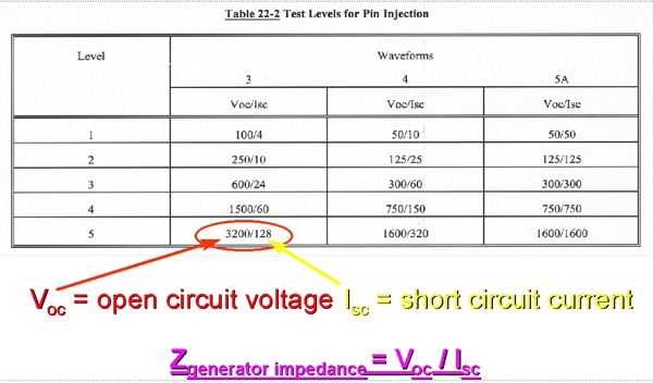
PIN injection. The transient is applied directly to the system interface circuits and is used to assess the dielectric withstand voltage or damage tolerance of the interface components. PIN injection waveforms are defined in terms of the test signal measured in an open circuit (voltage) and a short circuit (current).
Cable Bundle Single Stroke. Cable bundle tests are performed using an injection probe to couple transients. Tests are performed on fully configured functioning equipment to determine equipment survivability.
Voltage and current levels have to be monitored during the test process to ensure the test limit is not exceeded and/or the test level is reached.
Multiple Stroke
Multiple stroke waveforms are applied to determine the electromagnetic compatibility (EMC) of systems, subsystems, and equipment. The multiple stroke waveform set comprises a series of 14 transients, the first of which represents the initial stroke (component A), followed by 13 transients at 50% of the first which correspond to restrikes (component D) on the airframe. Multiple stroke transients are applied to cable bundles only using an injection probe.
Multiple Burst
Multiple burst waveforms are also used to determine the electromagnetic compatibility (EMC) of systems, subsystems and equipment. The multiple burst waveform set is characterized by randomly spaced groups of 20 low amplitude current transients. Each impulse contains rapidly changing currents.
Multiple burst transients are derived from lightning leader progression or branching. The pulses are most intense at the time of initial lightning attachment to the aircraft structure. Transient responses arising from the magnetic (H) field of the external environment will also occur in the induced multiple burst sequence. The predominant waveform responses are the damped sinusoidal waveforms in a frequency range from 1 MHz to 10 MHz.
TEST EQUIPMENT REQUIREMENTS
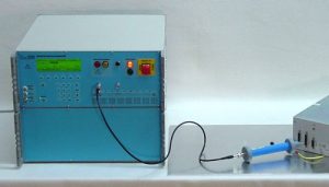
Avionics testing to DO-160 requires distinct impulse test types with very diverse waveform characteristics and energy content. Most waveforms are only slightly influenced by the connection leads, and therefore, a generator source impedance can be directly expressed as Voc / Isc.
Using this information and following the clearly defined calibration setup in DO-160, it is relatively straightforward to design a generator for PIN injection tests.
Table 22-2 of DO-160, specifies Voc = voltage amplitude in open circuit and Isc = current amplitude in short circuit “at the injection point.” This should be interpreted to include connection cables and test tips required to deliver the impulse to an EUT.
DO-160 introduces a concept that requires some further explanation here. All cable bundle tests take into account the potential influence of EUT cabling on the impulse focusing only on the amplitude by defining parameters of “I Test” and “V Test” or “I Limit” and “V Limit” values.
A “Test” value is the ideal that should be reached, if possible. The “Limit” value is the maximum allowable value measured in a cable bundle to prevent over stressing the EUT. When this occurs, the test is deemed to have been completed.
Often, the “Test” and “Limit” values are misinterpreted as defining the generator impedance. In fact, this can be said to be the system “virtual impedance” which includes the generators, cables and couplers. As we have already established, generator impedance is given ONLY by the PIN injection requirements.
Because the cable bundle impedance is so significant, it naturally follows that type and routing of the cable, or the impulse injected can also have a big influence as to whether the “Test” or “Limit” value is reached first.
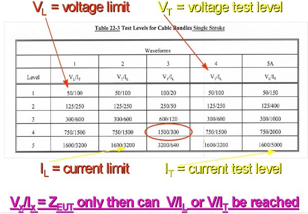
From Table 22-3 of DO-160, we can deduce an EUT impedance of 5 ohms for Waveform 3. In fact, this tells only half of the story as the following example illustrates.
Characteristic impedance for a cable is given by:
XL = 2Πf x L
For a multi-wire cable of 3.3-m length (specified in DO-160), the inductance approximates to L = 1 µH.
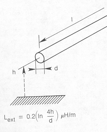
At 1 MHz, this equates to an impedance XL = 6.3 Ω. This is very close to the 5 Ω used by the standard. At 10 MHz and using the same cable, the situation changes as follows: XL = 62.8 Ω. Because of these application limitations, multiple stroke Level 5 waveforms can only be reached under certain conditions.
Waveform 1 and Waveform 5 specify voltage as “Limit” and current as “Test;” this is equivalent to an EUT presenting a maximum impedance to the test system. For Waveform 2, Waveform 3, and Waveform 4, current is specified as “Limit” and voltage as “Test;” this is equivalent to an EUT presenting minimum impedance to the test system.
Waveform 3 (1 MHz and 10 MHz) and its application according to DO-160 has some special parameters which make design and use of a suitable generator somewhat complex. For example, this type of damped sine wave can only be reliably generated using an electronic switch. This waveform is defined as a hybrid; both voltage and current have the same form, with relatively high values for voltage and current (3,200 V/128 A PIN injection). Following the earlier discussion, this defines the generator output impedance to be Zout = 25 Ω. Now, we come to the next problem. Because of the relatively high frequencies involved (1 MHz and 10 MHz), it is necessary to use co-axial cable to transfer energy from generator to coupling device. This method reduces waveform distortion and interference with the environment. For the 10-MHz signal in particular, use of 50-Ω co-axial cable raises the effective generator impedance and the cable capacitance loads the generator, so that a much higher output voltage is needed to be able to drive the required current levels. Unfortunately, the simple solution of using a lower impedance co-axial cable does not help because lowering the cable impedance increases the capacitance and diverts energy away from the coupling device.
Further adding to the test equipment designer’s woes, is the fact that the EUT cable impedance will never be zero Ohm. Cable bundles usually present an inductive impedance to the generator and coupler. Theoretically, it should be possible to lower the generator impedance but for practical reasons, this is not possible.
Due to all these factors and under normal applications, voltage can be reached in the test circuit but not always current. The following examples illustrate this point.
Single wire with inductance approximately 1 µH:
Excited by WF3 at 1 MHz
Voltage = 2Πf x LI = 6.28 x 1 106 0.9 10-6 640 A = 3.6 kV
Cable bundle with reduced inductance approximately 0.5 µH:
Excited by WF3 at 1 MHz
V = 2Πf x LI = 6.28 x 1 106 0.5 10-6 640 A = 2 kV
Cable bundle with reduced inductance approximately 0.5 µH:
Excited by WF3 at 10 MHz
V = 2Πf x LI = 6.28 x 10 106 0.5 10-6 640 A = 20 kV!!!
The test voltage from DO-160 of 3200 V will be reached before the current limit.
After examining all these facts and taking into account the potentially endless variety of EUTs, it is relatively easy to see that a complete DO-160 test system to meet section 22 requires more than one impulse generator.
DO-160 STANDARD COMPATIBILITY
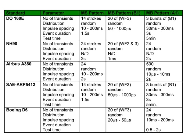
Aircraft OEMs exist in a highly competitive marketplace, where the pace of change and new technologies are introduced at an increasing rate to meet ambitious fuel consumption and range specifications. Each aircraft OEM therefore needs to “tailor” their test requirement to meet an individual aircraft or aircraft family’s specialist requirements.
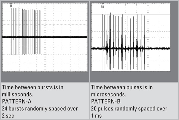
Table 2 is a summary of some current requirements. Table 3 is an example of Multiple Burst (MB) waveform relationship (NH90 helicopter).
CONCLUSION
Experience dealing with users of avionic test systems has shown that the majority of avionics test requirements are at relatively low amplitudes. Even the increasing use of composites has not affected the test amplitudes to any great extent, but in certain circumstances, the waveform definitions have changed. The increasing use of composites in airframes changes impulse characteristics induced onto cables and electronics. Waveshapes previously specified as predominantly currents have been translated into voltage requirements because current paths through cable shields with return via the aircraft structure, may no longer be available.
The latest information from research and test experience, shows that frequencies other than the 1 MHz and 10 MHz can be present in civilian aircraft. In reality, platform resonances at many frequencies up to 17 MHz have been encountered with exceptional resonances at 30 MHz being recorded.
As usual, test standards are running behind the fast pace of technological change and DO-160F is already being prepared for issue during 2007.
BIBLIOGRAPHY
- RTCA/DO-160E: Environmental conditions and test procedures for airborne equipment. Section 22: Lightning Induced Transient Susceptibility. December 9, 2004.
- Erik Borgstrom. “EMC requirements for avionics: RTCA DO-160D, changes 1 and 3.” ITEM 2002.
- EUROCAE Aircraft Lightning Environment and related test waveforms, Document ED-84 Edition 2. May 18, 2001.
- Martin Lutz, Reto Casanova. “Induced Lightning Testing of Avionics – with Single Stroke, Multiple Stroke and Multiple Burst.” EMC Partner AG, Laufen Switzerland.
- MIG-OS-MB Test Guide. EMC Partner AG, Laufen Switzerland. August 6, 2004.
- MIG 0600MS Test Guide. EMC Partner AG, Laufen Switzerland. June 9, 2003.
- MIL-STD-461E: Requirements for the control of electromagnetic interference characteristics of sub-systems and equipment. August 20, 1999.
- Terri He and Brian Kuhlman. “Investigation of test methods for DO-160 qualification tests.” The Boeing Company. 2003.
ABOUT THE AUTHOR
Nicholas Wright was educated at Worcester College, England. He has worked on military projects for the UK M.O.D, Marconi and GEC Avionics. Moving into the field of EMC, he has held posts as product manager and regional sales manager, culminating in his current position as international sales manager for EMC Partner based in Switzerland.


