1. Introduction
The past decade has witnessed both a leap forward in technology and market expansion of the global electric vehicle (EV) industry [1]. With Tesla leading the market, followed by traditional vehicle original equipment manufacturers (OEMs) such as Volkswagen, PSA, and Toyota, to name just a few, the electrification of the automotive industry has been advancing at a fast pace [2].
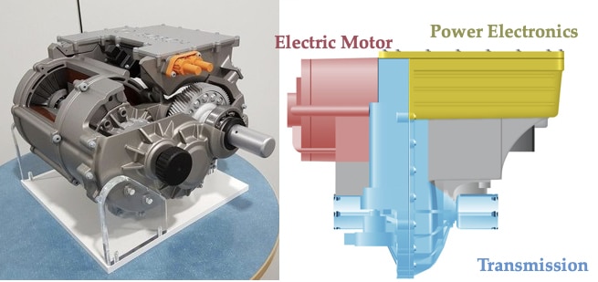
The beating heart of an EV is its electric drive unit (EDU), also referred to as powertrain, which consists of an electric motor, a power electronics module, and a transmission. This is often referred to as the three-in-one unit. The three-in-one EDU from Bosch is shown in Figure 1 [3]. In this case, the transmission is sandwiched between an electric motor and the power electronics module.
The OEMs often outsource components of a vehicle to Tier-1 suppliers allowing them to focus their resources on vehicle system integration and manufacturing. The suppliers, when receiving the product specification and requirement, design the bespoke parts for the OEMs. For key differentiator components such as the EDU, the battery pack, and software integration, it is often in the OEMs’ own interests to keep the design in house, which gives them an advantage over their competitors.
For automotive applications, all components must be designed to meet OEM’s unique design specifications. These specifications include function, mechanical, environmental, electrical, electromagnetic compatibility (EMC), functional safety, and more. In addition to the size, cost and performance challenges, automotive design engineers are now facing the ever-challenging thermal and EMC requirements.
This paper focuses on the EMC challenges of EDU design. The EMC design of such a complex system requires lots of compromises. Engineers should all be familiar with the compromise associated with good engineering. The compromise must be based on understanding. In order to build up a common understanding, this paper explores the EMC design of the EDU from the angle of electric machines, power electronics, and thermal design.
Background
A survey carried out by the International Energy Agency in 2017 concluded that more than 40% of global electricity production was consumed by electric motors [1]. One can already foresee the increase to this percentage due to the economy of scale behind electrification.
Improving the compact design of an EDU will achieve a smaller size, lighter weight, and better thermal performance. The unit must also conform to EMC standards, a design process that is often (incorrectly) regarded as ‘black magic’ by designers.
To demystify the EMC issues that design engineers are facing, this paper focuses on the design aspect of EMC. One of the most important lessons is to design a system with EMC in mind from the get-go. This approach avoids or reduces the time and resources spent on finding and fixing EMC issues during the testing phase.
Testing to verify EMC conformance is always expensive and time consuming. Any EMC troubleshooting required during the verification testing phase will inevitably make a huge impact on the project delivery plan. Sometimes, an unsolved EMC issue leads to a failed product launch, causing a financial loss of millions of dollars.
Drawing on know-how in state-of-art electric machines and power system design, combined with experiences in the field of EMC, this article highlights the design challenge of an EDU, outlines crucial design blind spots, and addresses key EMC issues. To cover the full scale of an EMC design of an EDU in one paper is ambitious, but this paper should give all designers in the field a broad idea of good, cost-effective EMC design, and how to avoid EMC issues that could potentially jeopardize the project delivery plan.
Demystifying EMC—the Breakdown of an EDU
Figure 2 demonstrates the electric system of an EDU. All the key components are shown and marked. A detailed breakdown of an EDU module is then presented.

3.1 Electric Motors
The common motor topologies used in automotive EDUs are listed below:
- Permanent magnet brushless DC machine, as the one seen in Nissan Leaf, Figure 3 (a)
- Induction motor, like the one seen in early models of Tesla Model S, Figure 3 (b)
- Switched reluctance motor, as the one seen in Ricardo prototype, Figure 3 (c)
- Permanent reluctance motor, as the one seen in Danfoss Visedo, Figure 3 (d)
- Axial flux motor, as the one seen in YASA motor, Figure 3 (e)
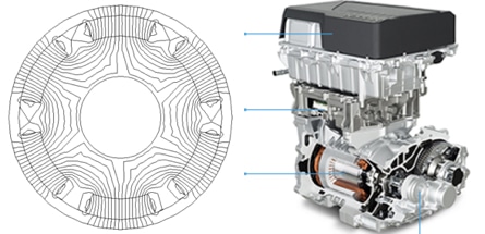
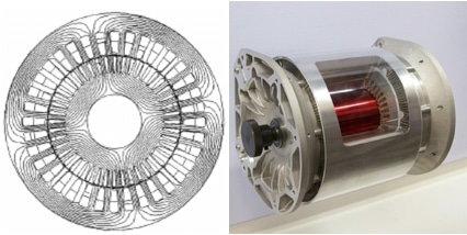
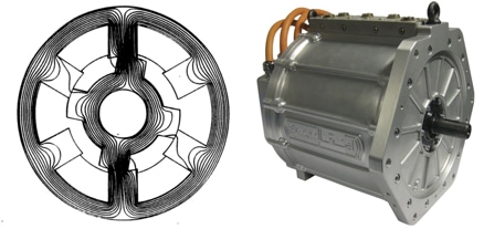
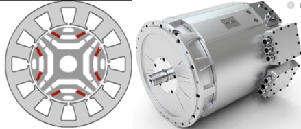
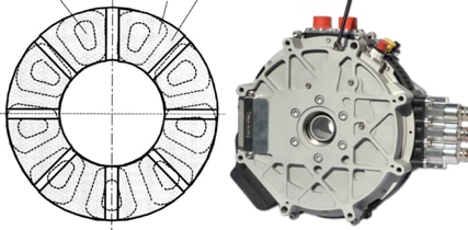
Combined with high torque density and high efficiency, permanent magnet machines dominate the EV electric motor sector. The prices of the rare earth materials, although not cheap, have still been kept low enough during recent years, which has enabled the leading position of permanent magnet motors.
It is not (yet) a general practice to take EMC into consideration when designing an electric motor. Size, weight, cost, and thermal efficiency are the main focuses, whereas EMC is not even a design constraint. However, from the overall EDU system perspective, it is strongly recommended that motor design engineers must pay attention to certain EMC aspects in order to minimize noise interference and achieve better control accuracy. The EMC aspects of electric motor design are listed below:
3.1.1 Busbar
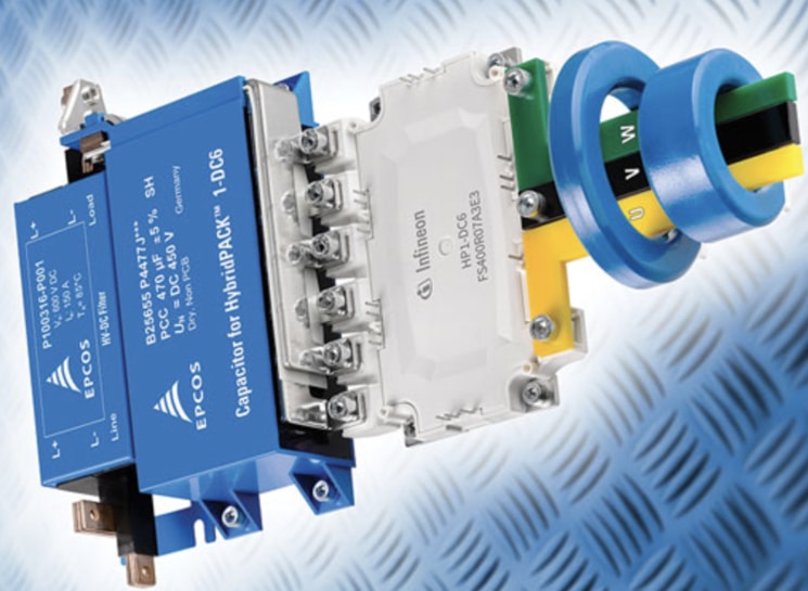
Instead of using cables, busbar design is predominantly seen in EDU design due to its strong mechanical structure, high current density capacity, and ease of manufacturing. From the EMC perspective, busbar design is also preferred as it effectively shortens the cable length between the high-power switches and the motor terminals. The mechanical stability of busbars also eliminates the EMC testing inconsistencies caused by random arrangements of power cables. A busbar configuration is shown in Figure 4, with TDK common mode choke assembled.
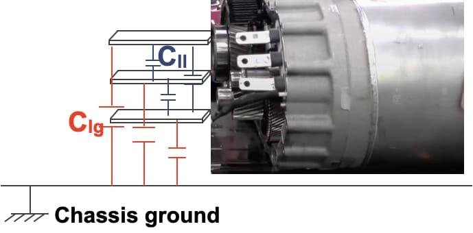
However, this is not to say that the line-to-line capacitance (Cll), or the line-to-chassis ground capacitance (Clg) are eliminated or reduced. In fact, in some cases, the parasitic capacitance can be increased if good EMC design has not been taken into consideration. It is important to recognize that a capacitor is by definition a conductor geometry that stores electric field energy. Conductors, between which there’s a dielectric material (whether it is air, glass epoxy, conformal coating, etc) form a capacitor [4]. The basic equation of a parallel plate capacitor can be found in Equation 1, where A is the area of the conductors in square meters and h is their spacing in meters. e0 and eR are the vacuum permittivity and relative permittivity, respectively.

This equation can be used to calculate the capacitance of most commercial capacitors. It can also be used for determining the capacitance between busbars (Cll) and the capacitance between busbars and enclosure (Clg). Line-to-line capacitance is related to differential switching noise whereas line to chassis ground capacitance contributes to the common mode noise [5]. It should be no surprise that a common busbar is often designed with the least loop area by ‘interleaving’ laminated busbars. Therefore, the beneficial effects of this design on parasitic series inductance (as well as on parasitic shunt capacitance) can be achieved.
A demonstration of the parasitic capacitors of busbars can be found in Figure 5.
3.1.2 End Winding
Both amplitude and waveform shape of generated voltages and magnetomotive force (MMFs) of an electric motor are determined by the winding arrangement. There are many different types of winding configurations, among which, single-tooth winding has become more and more popular with switched reluctance machines and permanent magnet machines due to its simplicity and ease of manufacturing.
This type of winding also achieves very short end windings, which limits the leakage flux coming out of the motor. Therefore, the single-tooth winding is a preferred option from an EMC point of view. Short ending winding means less parasitic capacitance between the winding and the vehicle chassis (‘ground’), hence less CM noise generation.
The magnetic flux generated by motor operation is mostly contained within the motor frame, but the leakage flux from end windings are not contained. Exposed to free space, the flux can easily radiate.
Motor position sensors are generally located close to the stator end windings or rotor ends. There are two types of sensors, namely the optoelectronic type and the Hall Effect type. Optoelectronic position sensors enjoy the benefit of low cost and they are immune to electromagnetic interference. But they are very susceptible to dusty/dirty environments, hence not a good option for automotive application. The Hall Effect type position sensors, on the other hand, don’t mind such environments, but they are susceptible to stray magnetic fields. Therefore, having a short winding configuration can also reduce the noise coupling effect of leakage flux, which helps achieve better accuracy of position sensors.
3.1.3 Turn to Turn
It is a misconception to treat windings just as inductors. Although, this representation is generally good enough for motor and power system performance analysis. It fails to address the issues associated with EMC. Every winding configuration in the stator has parasitic capacitance caused by turn-to-turn proximity, called interwinding capacitance. Here, the concept of parasitic capacitance is emphasized again. During the motor operation phase, the current in the winding regularly and rapidly increases and decreases. The result is rapidly-changing magnetic fluxes that create rapidly-changing voltages, and these fluctuating voltages create parasitic noise currents in the interwinding capacitances.
3.1.4 Stator to Rotor
The same principle that is drawn from previous sectors can be applied to the stator to rotor parasitic capacitance.
3.1.5 Bearing
Bearing current is one of the causes of bearing deterioration in electric motors, and in extreme cases has been seen to shorten bearing lifetime to 10% of what was expected. Traditionally, a parasitic capacitance between the shaft and winding was used to model this effect. In this article, a new model of back-to-back Zener diodes in parallel with the shunt capacitor (seen in Figure 6) is proposed.
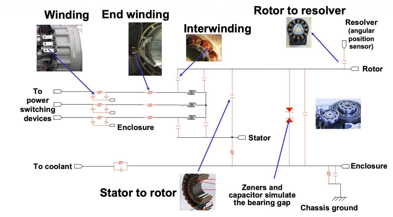
Bearings have a moving metal ball or roller and a fixed metal shell. Grease sits between the two parts, but it is very thin and therefore has a high capacitance and can carry high displacement current. Because it is thin, and because the bearings are not perfect, there can be an occasional electrical breakdown and even direct touching of the two metal parts. Therefore, the bearing current is partly capacitive, which gives a pulse of current every switching transition and partly random high current spike. By using this new model, the random spiky bearing current can be simulated.
The parasitic parameters of an electric motor are demonstrated in Figure 6.
3.2 Power Electronics Module
3.2.1 Power Electronics Devices
The emerging wide-band-gap (WBG) material power semiconductors such as silicon carbide (SiC) and gallium nitride (GaN) devices are game-changing devices. They can exceed the limit of silicon (Si) and are used to pursue ground-breaking high frequencies, high efficiencies, and higher power density power conversion [6]. There is no doubt that WGB devices using SiC or GaN will be replacing Si devices such as IGBTs and MOSFETs in EDU designs in the near future.
The faster switching characteristics of WBG allow improved system efficiency due to reduced power electronics device loss (both conduction and switching losses). It can also bring great benefits to the electric motors. For current control, with the availability of high-speed switching devices, low inductance motors become feasible. The winding configuration of low inductance motor has a smaller number of turns, so it is easier to design, and also has benefits for cost, weight, and manufacturing ease points of view.
The problems that are associated with high switching frequency WBG devices are mainly EMC and thermal. Since the wide-band-gap devices enjoy very low switching and conduction loss, the biggest design obstacle for a power electronics engineer is the EMC challenge. The power electronics devices act as a noise source.
The switching speeds of typical WBG devices can easily exceed 10V/ns [7]. ESL (equivalent series inductance), ESR (equivalent series resistance), and parasitic capacitance can be estimated based on the package of the device [7]. Traces, pads, and PCB layout add another layer of complexity to the EMC design as they are treated as transmission lines.
From the circuit theory point of view, the parasitic inductance and capacitance of the device package, the PCB layout and the connections contribute to noise voltage and current spikes observed in the switching waveform (see Figure 7 [7]). From the point of view of transmission line theory, the oscillation of the switching waveform is indicative of the fact that electromagnetic energy can only travel at a limited speed, which is less than the speed of light (often half in a glass epoxy dielectric material [4]). This means that many backward wave reflections and forward transmissions are needed to deliver the energy required by the motor.

The envelope of the spectrum of a step function pulse is shown in Figure 8. The switching speed is of more importance than the switching frequency. The harmonics (single-frequency sine waves, calculated using the Fourier Transform) that make up this square wave will have amplitudes that fall off in proportion to frequency up to a frequency of 1/πt, where t is the rise time or fall time, whichever is the smallest. This is the -20 dB/decade region in Figure 7. Beyond this frequency, the harmonic amplitudes fall off proportional to the square of frequency [8], the -40dB/decade region in Figure 7.
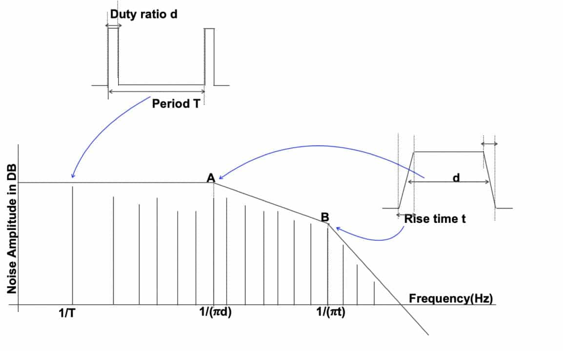
By slowing down the rise times/fall times of the switching devices, the levels of harmonic noises will be reduced. But this approach can be counter-productive for WGB devices, as it can fail to fully utilize their potential. Therefore, selection of a low ESL package, and designing a good PCB layout, become the key methods of controlling the electric fields and noise emissions.
Design engineers should aim to layout the PCB so the parasitic capacitances between its traces and components and the rest of the EDU are minimized. The common-mode current depends on the parasitic capacitance, Cpar, and the voltage switching speed—as shown in Equation 2, below.

where ICM is the common mode current, Cpar is the parasitic capacitance, dV/dt is the switching speed.
3.2.2 SiC Diode
A SiC PN junction diode suffers from reverse recovery in much the same way that a Si PN diode does. MOSFETs have an intrinsic PN body diode that is an unavoidable part of the MOSFET’s structure. SiC MOSFET body diodes are usually not great in terms of the conduction loss and switching loss.
Schottky diodes don’t use minority carrier (hole) conduction like PN diodes, so don’t have the reverse recovery issue. Therefore, SiC Schottky diodes are often used in parallel with SiC MOSFETS to bypass their intrinsic PN body diodes.
3.2.3 Decoupling capacitors
Decoupling capacitors are widely used to filter out the switching noises caused by the switching devices. When selecting and placing decoupling capacitors, the following rules apply [9]:
- Decoupling capacitors shall be geometrically close to the switching devices
- Small capacitors (in terms of both value and physical size) are recommended, generally, the smaller the size, the less ESL of the capacitors
- Different values of decoupling capacitors should be used, with the ratios between values no greater than three (e.g. 100 nF, 330 nF, 1 µF, 3.3 µF, etc.). The smallest value capacitors should be placed closest to the switching devices
- Avoid oscillation due to the natural frequencies of the decoupling capacitors, sometimes this requires damping
- Arrange capacitor orientation, so as to achieve maximum decoupling
3.2.4 DC Link
DC link capacitor
The DC link (see Figure 2) design involves DC busbar design and DC link capacitor design. For DC busbar, the design should follow the same principle as the design in Section 3.1.1 to reduce the loop area.
It is a misconception to treat energy storage capacitors and decoupling capacitors separately. Essentially, they serve as an energy source and exhibit transmission-line behavior. A low ESR and ESL film type capacitor at the DC link plays a crucial role in reducing both the differential and common mode noise. The capacitor should be geometrically close to the noise sources, which are the high-speed switching devices, to provide a low impedance loop for the noise current path.
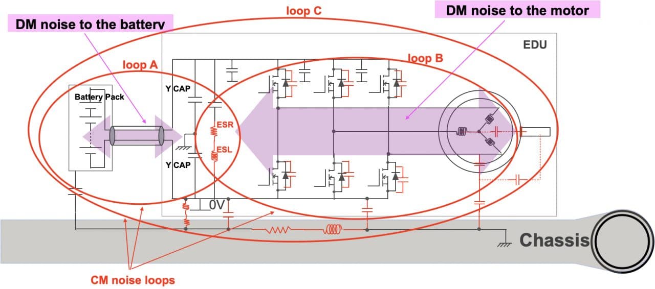
An example of this arrangement can be found in Figure 4 where EPCOS film capacitors are connected to an Infineon SiC power-switching module. The differential mode (DM) noise loops and the common mode (CM) noise loops are demonstrated in Figure 9. As it can be seen, larger value of ESR and ESL of the DC link capacitor will increase the size of the common mode noise loop (Loop C), hence increase the conducted noise. A larger loop also radiates more easily.
Class Y-Capacitors
Class Y-capacitors are often placed to filter the common mode noise at the front end of an EDU (as shown in Figure 2). The performance of Y-capacitors in an EDU application has been limited due to the limited energy that is allowed to store in the capacitance in an EV system. For high voltage safety reasons, the energy stored in the capacitor cannot exceed 0.2 J [10]. The energy stored in a capacitor, E, can be calculated using Equation 3.

Where C is the capacitance in farads and V is the voltage in Volts.
As the engineering trend is to increase the operating voltage, in the near future, 800 V or 1,200 V system will be available in the market. It can be seen that for an increased voltage level, due to the square relationship, the capacitance value that one needs will be significantly reduced.
3.3 Heat Sink and Enclosure
Thermal design is crucial for EDUs as both electric motors and power electronics modules rely on constant cooling to achieve high efficiency and reliability. The efficiency of the transmission is also temperature dependant.
When it comes to EMC, certain aspects of the thermal design, such as effective cooling area, the dielectric constant of the thermal paste, coolant material, bonding, and connections are all relevant. Details of a good heat sink and enclosure design can be found in [11].
4. Conclusion
This paper presents the EMC design aspects of an electric drive unit. An EDU consists of a DC link, an electric motor, a power electronics module, and the transmission line from it to the motor, all packed into a single enclosure.
By breaking down the EDU to a subsystem level, engineers can see the details and form a solid understanding of EMC design. Details such as parasitic parameters associated with motors and electronics are presented to give readers an appreciation of the interference source and path. Recommendations on design, therefore, are presented in a structural way.
As mentioned in the beginning, this brief paper does not aim to cover every aspect of the EMC design as this is not practical. In particular, topics such as filtering, grounding, and shielding are not covered, but all of the necessary design details are covered by references listed in the Bibliography.
Bibliography
| [1] | t. Economist, “As electric motors improve, more things are being electrified,” the Economist, no. Sep 16th, 2017, available: https://www.economist.com/science-and-technology/2017/09/16/as-electric-motors-improve-more-things-are-being-electrified. |
| [2] | P. C. Joe Miller, “VW chief defies sceptics with ambitious plans to overtake Tesla,” the Financial Times, March 2020. [Online]. Available: https://www.ft.com/content/c90449ea-58eb-11ea-a528-dd0f971febbc. |
| [3] | Bosch, “Bosch Mobility Solutions,” [Online]. Available: https://www.bosch-mobility-solutions.com/en/products-and-services/passenger-cars-and-light-commercial-vehicles/powertrain-systems/electric-drive/eaxle/. |
| [4] | Tim Williams, Keith Armstrong, EMC for Systems and Installations, Newnes, 1996, available: https://www.emcstandards.co.uk/keithsbooks. |
| [5] | G. L. Skibinski, R. J. Kerkman and D. Schlegel, “EMI emissions of modern PWM AC drives,” IEEE Industry Applications Magazine, vol. 5, no. Nov.-Dec, pp. 47-80, 1999. |
| [6] | Z. Liu, B. Li, F. C. Lee and Q. Li, “High-Efficiency High-Density Critical Mode Rectifier/Inverter for WBG-Device-Based On-Board Charger,” IEEE Transactions on Industrial Electronics, vol. 64, no. 11, pp. 9114-9123, 2017. |
| [7] | AN2017-46, “CoolSiCTM 1200 V SiC MOSFET Application Note,” Infineon white paper, 2018. |
| [8] | R. Morrison, Digital Circuit Boards: Mach 1 GHz, WILEY, 2012. |
| [9] | K. Armstrong, EMC for Printed Circuit Boards: Basic and Advanced Design and Layout Techniques, Nutwood UK Ltd, 2011, available: https://www.emcstandards.co.uk/keithsbooks. Updated and improved content is available: https://www.emcstandards.co.uk/essential-pcb-designlayout-techniques-for-cost and https://www.emcstandards.co.uk/advanced-pcb-design-for-cost-effective-si-pi-an |
| [10] | “Global Technical Regulation on the Electric Vehicle Safety (EVS),” United Nations, 3 May 2018. |
| [11] | K. Armstrong, EMC Design Techniques for Electronic Engineers, Nutwood UK Ltd, 2010, https://www.emcstandards.co.uk/keithsbooks. Updated and improved content is available from https://www.emcstandards.co.uk/online-training. |


