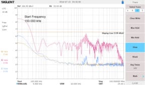
Figure 4 – The results with the 100 uH inductor installed (blue trace) looking from 150 kHz to 150 MHz. The red trace is the unfiltered noise and the yellow trace was the ambient baseline noise. The display line is the approximate emissions limit.
By Kenneth Wyatt, Wyatt Technical Services LLC
More of my clients are starting to use small third-party DC-DC converters to provide the multitude of voltages required for today’s processor and DDR RAM ICs. While these are convenient to drop onto a circuit board, they can be quite a source of radiated and conducted emissions – especially those that switch in the MHz range.
I recently published an article on how these converter circuits can generate harmonic noise all the way up to 1 GHz, and above, severely compromising RF receiver sensitivity in the wireless telephone bands [1]. Kevin Slattery and Harry Skinner called this “Platform Interference”, in their book, Platform Interference in Wireless Systems – Models, Measurements, and Mitigation [2].
One example of this type of “drop-in” DC-DC converter is manufactured by Murata and we’ll use their model UWE-24/3-Q12, which is an “Eighth Brick” power supply that can take 9 to 36V and convert it to 24V at 3A (Figure 1). My client was using three of these converters on a product and was measuring a high level of radiated emissions, as well as observing broadband noise throughout his system all the way through 150 MHz.
If you read the manufacturer’s specification sheet, you’ll generally find that to “pass” EMI will require “additional filtering”, and this converter is no different. In this case, the additional filtering required to meet EMI limits was not described. I decided to bring one of these back to the lab and try some experiments to attempt to quiet the EMI.
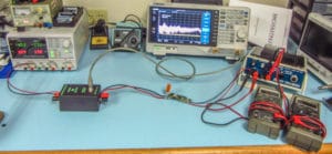
To do this required some instrumentation. I used a Siglent Technologies SPD3303C three output power supply, a Tekbox Technologies TBOH01 5uH LISN, A Tekbox Self-Powered Active Load, and a Siglent Technologies SSA3032X spectrum analyzer. All this gear is available from the U.S. distributor, Saelig Electronics [3]. The active load was really handy, because I could dial in the exact load current I wanted…in this case 0.5 amps, to avoid cooling issues. I connected a couple of Fluke DMMs to monitor the output voltage and current (Figure 2). The spectrum analyzer picked off the conducted emissions via the LISN.
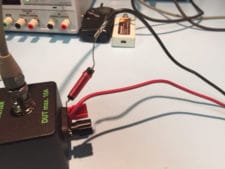
After trying some inductors and common-mode chokes I had on hand, I determined that simply placing a 100uH inductor in series with the input terminal was enough to quiet the emissions rather drastically (Figure 3).
Figure 3 – A 100 uH inductor was all that was required to dramatically reduce the conducted emissions.
Figure 4 shows the result. The yellow trace was the ambient (baseline) signal level. The red trace was unfiltered (no inductor) and the blue trace was with the inductor added in series with the input voltage to the converter.
The addition of a single inductor nearly reduced the conducted emissions down to the noise floor of the measurement.
Conclusion
Many EMI tests may be conducted right at the bench top. Evaluating various vendor products, such as DC-DC power supply converters, is always wise, prior to committing to a PC board design. It’s also wise to verify EMI performance as well as reading the “fine print” within the product specification sheet. Very often claimed EMI performance will require additional components.
References
[1] Wyatt, Platform Interference, http://www.edn.com/electronics-blogs/the-emc-blog/4441086/Platform-interference
[2] Slattery and Skinner, Platform Interference in Wireless Systems – Models, Measurements, and Mitigation, https://www.amazon.com/Platform-Interference-Wireless-Systems-Measurement/dp/0323281451/ref=sr_1_2?ie=UTF8&qid=1450492921&sr=8-2&keywords=Platform+interference
[3] Saelig Electronics, http://www.saelig.com