Martin Wiles, Vince Rodriguez, ETS-Lindgren
Developments within standards community has led to new chamber validation procedures above 1 GHz and alternative test methods using FARs.
INTRODUCTION
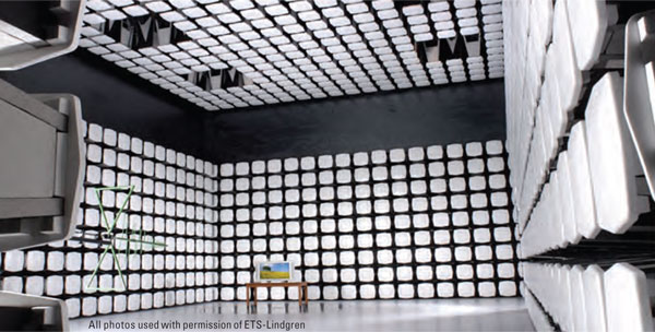
Anechoic chambers are used today for performing EMC measurements according to a variety of published EMC standards. There are many different fields of application, including consumer electronics, automotive, aerospace, military, medical, telecommunications and others. Standards are developed and published worldwide by different organizations resulting in different requirements and consequently different chamber types.
EMC anechoic chambers, especially those with conductive floors (called semi-anechoic chambers or SAC), are primarily used for testing radiated emissions (RE) in the frequency range from 30 to 1000 MHz and radiated immunity (RI) from 26 or 80 MHz to 1000 MHz, with extensions to 6 GHz, 18 GHz, or even 40 GHz with RE measurements becoming more frequent. While there are standards that call for radiated measurements down to the low kHz or even to the low Hz range, these standards do not specify any need for absorption or anechoic behavior as the chamber validation criterion starts at 30 or 80 MHz. In most cases, at these low frequencies where current absorber technology cannot deliver any level of absorption, the chambers are going to be too small (electrically) for resonant modes to appear.
Different methods and criteria for validating chambers and performing EMC measurements for testing immunity or capturing emissions are standardized, including test distances, field levels, emission limits, pass criteria, equipment set up and so on. There are, however, cases where standards are vague regarding the chamber performance. For example, some automotive component standards mention a given level of reflectivity at the EUT area but do not provide any specific method to test this requirement. In those cases, some interpretation of the wording of the standard is needed or consulting with the appropriate standards developers as to their intent or to better specify the requirements in a subsequent edition of the standard.
TODAY’S TECHNOLOGY
Fundamentally, the EMC anechoic chamber is a shielded room with RF absorber materials installed on the four walls and ceiling and possibly on the floor. The design of EMC anechoic chambers is dictated by the standards and the available technology. This section describes some of the main components with a focus mainly on the RF absorber technology.
RF SHIELD TECHNOLOGY

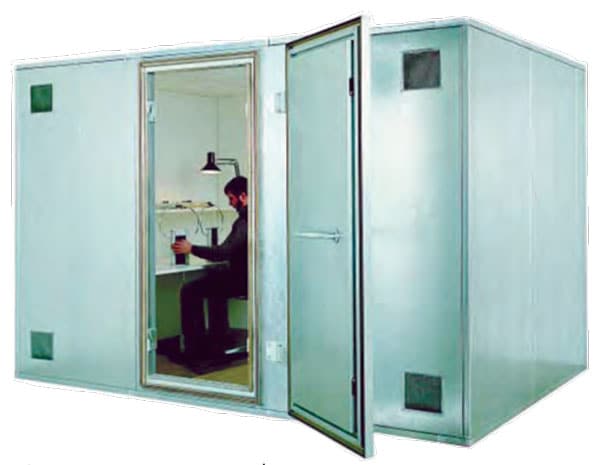
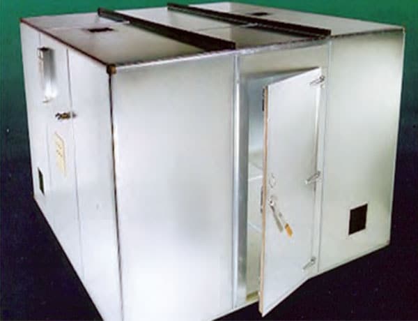
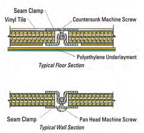
The chamber itself will almost always be a shielded room or Faraday cage, which means that it is an isolated RF environment that is not disturbed by external interference and in turn does not disturb the external environment itself. The shielding specification is typically defined from 10 kHz to 18 GHz (and sometimes to 40 GHz) with acceptance testing methods described in IEEE 299 [1] or EN 50147-1 [2]. The user will typically define the required shield attenuation levels.
Typical values for the two main types of shielded panel technology are given below.
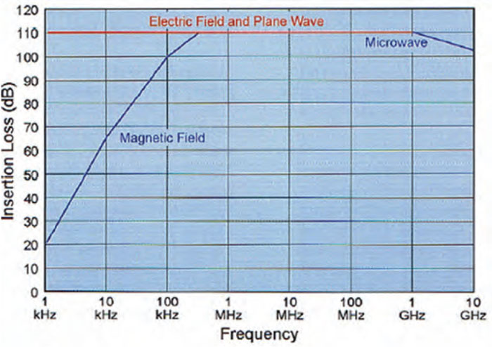
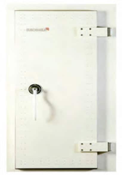
Other components of the shielded room that we will mention briefly are the door, whose quality and size will significantly influence the overall cost and performance of the shielded room, as well as RF filtering for electrical, data and other cabling that must be present in the room.
RF ABSORBER TECHNOLOGY

The RF absorber materials that line the surfaces of the shielded room play a major part in the chamber design. There are three basic types of absorber available. These are summarized below.
- Microwave Pyramidal Absorber: The name may be misleading as this material is used down to 200 MHz or even 80 MHz, well below the traditional microwave range. This material is generally referred to as the traditional “blue stuff” or “blue foam.” This is a material where a substrate (usually polyurethane) is loaded with carbon. To achieve any level of absorption, the material must be of a certain electrical size from the base to the tip of the pyramid. Thus, it is commonly used at higher frequencies. There are, however, some chambers used for EMC where this material is still used. The original EMC chambers in the early 1980s used this material with pyramids having 2.4m in length in order to have usable undesired reflection suppression down to 30 MHz. More recently, multi-purpose chambers such as the Satellite-Antenna-EMC-Measurement chamber at the Laboratory of Integration and Testing (LIT) of the INPE (Brazilian National Institute of Space Research) used specially cut 1.8m pyramids to meet the EMC requirements as well as the absorption levels for antenna measurements over the frequency range of 500 MHz to 40 GHz.
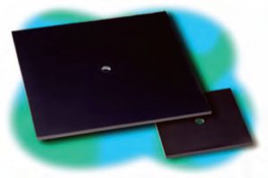
- Ferrite tile:In the 1990s, and even much earlier, ferrite tiles were introduced as a non-linear absorbing material. These are magnetic loss materials that are truly narrowband materials. For ferrites to work optimally, they need to be mounted on a metal backing and the spacing between the tile and the metal is critical. Tiles have excellent absorption characteristics given their low profile, usually 5 to 7 mm in thickness. Unfortunately, they stop being absorbers at frequencies around 1.5 GHz or even lower. Recently some manufacturers have introduced plastic pyramids injected with ferrite powders. These pyramids are short and provide good absorption in the 15 to 20 dB normal incidence up to 6 GHz and above, but for them to work at low frequencies they need to be matched with ferrite tile. This need for ferrite tile makes the chamber absorber very heavy and requires additional support for the chamber. It is important to note the savings in size usually does not offset the high cost of the material.
- Hybrid absorber was created as a combination of the two above technologies. This is not as simple as placing the traditional microwave “blue stuff” on top of the ferrite tile. By doing this combination, the ferrite performance is eliminated. Basically what happens is that as the EM wave penetrates the absorber, it starts traveling in a media that has a wave impedance very different from that of air. This wave impedance in the absorber is so different from that of the ferrite that the EM energy bounces off the ferrite without penetrating it, and penetration is the key to absorption. The problem is solved by adjusting the carbon content of the “blue stuff.” This can be done by reducing the carbon on the foam or by using hollowed pyramids. A different approach uses shaped coatings of lossy paint on polystyrene substrates to create a lossy impedance transform that makes a smooth change from the free space wave impedance to the wave impedance of ferrite. This transformation makes the ferrite more efficient at low frequencies. At high frequencies, the lossiness of the coating on the shape provides the absorption.
ABSORBER POWER HANDLING
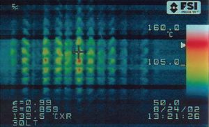
Before discussing anechoic chambers, the power handling of the absorber needs to be reviewed. This is important as exceeding the power handling might lead to destruction of the material and possible fire or emission of hazardous fumes. Traditionally, most manufacturers have used 200 V/m as the limit in their literature for EMC absorbers.
As military and automotive standards call for much higher fields, it is prudent to make some clarifications. The first is that most broadband absorbers convert EM energy into thermal energy which is then dissipated harmlessly into the chamber as thermal heat. Unfortunately, most foam materials are thermal insulators so they are not the best materials when it comes to dissipating the heat generated during absorption. The second is that tests run during the early 1970s on the traditional “blue stuff” showed that the material could easily handle power densities of 1 kilowatt per square meter which some manufacturers reduced adding a safety margin to 775 watts per square meter. This is about 600 V/m and this is for traditional foam. The foam used in hybrid materials having lower carbon content tends to have poorer absorption and less heat generation for a given field.
In 2004, tests were conducted at the anechoic chamber located at Delphi in Ciudad Juarez, Mexico. This chamber was used for CISPR 25 [3] testing. During the test levels of 600 V/m, and even 700 V/m, continuous wave (spot frequency) were generated close to the absorber and the foam was able to stand the levels without excessive warming.
More recently, work was performed by ETS-Lindgren at the Naval Surface Warfare Center in Crane, Indiana where the absorber was changed mechanically to cover more surface area and thus dissipate more heat. This specially cut absorber was able to withstand up to three kilowatts per square meter CW without the need for forced air cooling for a period of more than 20 minutes.[4]
Higher levels of power handling can be achieved with other materials such as more open cell products called filter foam (7.5 KW/sqm) or special high power materials made from a honeycomb-like substrate (> 10 KW/sqm). Even higher levels can be achieved by ventilating the materials.
Methods of measurement for absorber performance are described in IEEE 1128.[5] In particular, absorber evaluation is described in actual applications as in anechoic or semi-anechoic chambers and lined open area test sites.
ANTENNA TECHNOLOGY
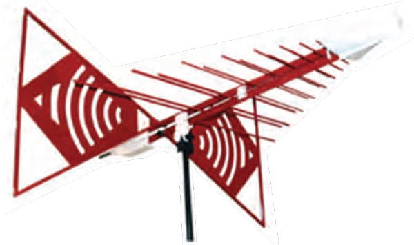
The antennas used for radiated emission field EMC testing are of key importance compared to the rest of the instrumentation. Over the past 10 years, antenna technology has clearly progressed and adapted to the different tests required by the standards. The older biconical and log periodic designs have seen the arrival of hybrid or combination antennas that can cover the entire frequency band of 26 MHz to 3 GHz or 80 MHz to 6 GHz in one sweep by combining and matching a biconical section to a log periodic section. Such combination antennas are often greater than a meter in width and length.

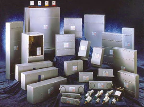
Radiated immunity testing will require low VSWR and high gain so that the smallest possible amplifier may be used to generate the required field. Here, combination antennas are the preferred technology if adequate power is not available.
Radiated emission testing requires high precision calibrated antennas (calibration is the key word here, not necessarily high precision which is not called out in most testing standards). Antennas have technically changed very little with biconicals and log periodics remaining the preferred technology between 30 MHz and up to 2 GHz, although there are some combination antennas which offer sufficient precision for compliance.
For faster testing and to minimize setup changes, combination antennas can be used for emission and immunity testing at the same time, so many EMC product measurements will be performed with combination antennas. However, chamber calibration according to radiated emission standards such as CISPR 16-1-4 [6] will prefer the higher accuracy (lower uncertainty of their calibrations) of the biconical and log periodic antennas. This is due to the smaller electrical size of the antenna and subsequent better definition of the log periodic antenna phase center. In addition, a combination antenna is about 1.5 m long and
has its low frequency section at the back. Assuming that the phase center is defined as the mechanical center of the antenna, the two low frequency sections will be separated at a 3 m distance by 3 m plus an extra 1.5 m (i.e., a 50% increase in the separation). For the most difficult chamber validation described by the NSA method, this has a not insignificant effect, and means that biconical and log periodic antennas are preferred at least for the chamber validation. The FAR (fully anechoic rooms) test methods, described later, have refined this method using a small biconical antenna, but this has led to other problems and these methods are likely to return to standard size biconical antennas.

For radiated immunity testing, the antenna is generally calibrated at 1 or 3 m separation between the source location and that of the receiving location in order to give an idea to system designers how much power can be developed with a given signal input.
For radiated emission testing, antennas are calibrated as pairs on a standard antenna calibration site that meets stricter NSA requirements than that for compliance testing according to ANSI C63.5 [8] [9]. Note that a new draft standard CISPR 16-1-6 [7] [10] solely on antenna calibration is currently being developed by IEC/CISPR and will reference ANSI C63.5 as one of the techniques for antenna calibration. This work has been under way for some time so that CISPR documentation will have an antenna calibration method. There is an emphasis to get this published this year or by early next year. Note that automotive testing will typically require developing higher field levels in the chamber which means different antennas will be needed.
FIELD PROBE TECHNOLOGY
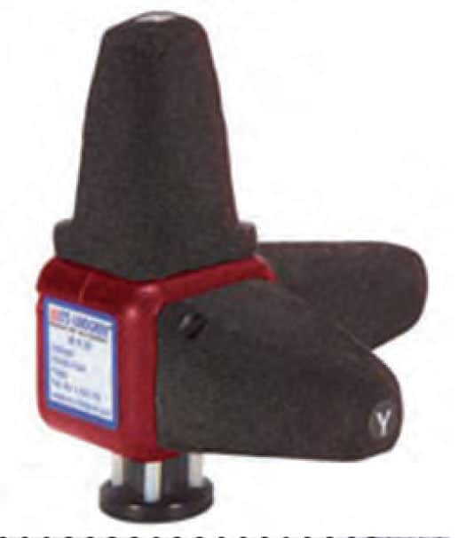
Another key component for field measurements is the field probe that is used to measure field strength during radiated immunity measurements. Important parameters for field probes include frequency range, in-band frequency response, dynamic range (maximum and minimum detectable field strength), isotropic response, response time, sample rate, and probe operation time. A laser powered probe may be appropriate in situations where long, uninterrupted and continuous operation is desired (to avoid battery charging between tests).
In certain applications, it may also be important to know how a probe responds to a modulated (AM/FM) field.
ANTENNA MAST TECHNOLOGY
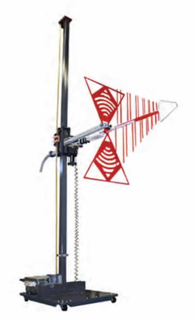
Radiated emission tests will require antennas to be mounted to a mast that will need to scan from 1 m to 4 m in height. The same antenna is often used for radiated immunity tests but will not scan. Other bigger antennas such as those used for automotive testing will have their own separate masts. Note that the ANSI C63.4 standard already stipulates that to meet requirements, “aiming” the antenna towards the EUT to maximize emissions above 1 GHz is required.
TURNTABLE TECHNOLOGY
Both radiated emission and immunity tests will require full azimuth rotation of the equipment under test (EUT). Metal topped turntables are typically installed in the chamber floor with their minimum size encompassing the entire EUT and its cables. Most turntables will have variable speed operation and can be operated by a remote controller that will also control the antenna mast.

III. EMC ANECHOIC CHAMBER TYPES
EMC anechoic chambers can be divided into different groups as follows:
- Partially lined:
- There are two types – The chamber surfaces are not fully covered with absorber per MIL STD 461 F [11] and RTCO-DO 160 [12] where parts of the walls and ceiling are a bare shield.
- Other partially lined chambers are fully covered with ferrite absorber but have a partial treatment of hybrid foam absorber for the higher frequencies. Hence, at frequencies below 1 GHz, these are semi-anechoic, but above 1 GHz they are partially lined with absorber in critical areas.
- Semi-Anechoic Chamber (SAC): The walls and ceiling are covered with absorber while the floor is a metal reflecting ground plane.
- Fully Anechoic Room (FAR): All surfaces are covered with absorber including the top of any turntable used where the turntable is at the same elevation as that of the bare floor of the chamber or room.
Depending on the need to fully comply with these standards, EMC anechoic chambers can also be further divided into two groups: pre-compliance (where testing is for research and development or where the purchase budget is limited) or full-compliance (where testing is for type approval). While a manufacturer who can fill the chamber test schedule with its own internal needs will focus the chamber requirement on its own product standards, an independent test lab must broaden its scope to be able to meet the requirements of as many standards as possible and to accommodate a wide range of products of different type and size. Throughput is often important in both cases and a quick change from one test set-up to another is an important part in chamber ergonomics.
- Pre-compliance compact chambers – RI pre-compliance/RE pre-compliance
- Compliance to IEC 61000.4.3 [13] radiated immunity
- Pre-compliance to the radiated emission standards such as CISPR 22 [14]
- Typical size: 7.2 m x 3.0 m x 3.0 m (L x W x H)
- Full compliance chambers – RI compliance/RE compliance
- Compliance to IEC 61000-4-3 radiated immunity
- Compliance to the radiated emission standards such as CISPR 22 and ANSI C63.4
- Typical sizes:
- 3m: 8.5 m x 6.0 m x 6.0 m; 2m diameter quiet zone
- 5m: 11.5 m x 7.0 m x 6.0 m; 2m diameter quiet zone
- 10m: 18.8 m x 11.6 m x 8.5 m; 3m diameter quiet zone

The most common type of chambers will be either the compact 3m (3m distance with a limited height scan for pre-compliant testing) or a full 3m (3m distance with full height scan) although many test organizations continue to have larger chambers up to 10 m types as the radiated emission limits in CISPR 22 are at 10 meter separation from the EUT for Class A; only Class B EUTs can be measured down to a 3 meter separation between 30 and 1000 MHz in particular circumstances. The compact chamber, if the standard allows the shorter separation distance, offers the advantage of being able to fit into the majority of buildings due to their limited height of 3m. The full 3m and larger chambers are typically part of a dedicated parent building purposely built in many cases to house the chamber.
Readers should also be aware that a current trend for older chambers with adequate shielding effectiveness, such as those installed in the 1980s, is to retrofit the chamber using current technology. In this case, old absorber is removed and replaced with new
absorber. The result is improved overall chamber performance and a larger interior footprint due to the smaller size of current absorber. [15]
IV. STANDARDIZATION
The main test applications for EMC are the consumer electronics, telecom, medical, automotive and military/aerospace industries. There is no single organization regrouping all the standards covering the above groups. The European Union (EU) has played a key role since 1992 in initiating a major overhaul in the standards available and has produced a number of directives such as the EMC Directive (2004/104/EC) [16], the Automotive Directive (2004/104/EC) [17], the Low Voltage Directive (73/23/EEC) [18], the R&TTE Directive (99/5/EC) [19], and the Medical Devices Directive (2001/104/EC) [20].
These directives require the testing of all products to be sold within the EU according to standards which have been either developed (mostly by CENELEC and ETSI), or which have been derived from existing standards. Standards organizations such as the IEC/CISPR are a major source of CENELEC EMC standards per an agreement between the IEC and CENELEC.
The IEC and its special committee known as CISPR publish voluntary generic, basic and product standards on a global level. It is extremely active and its newly published documents need to be monitored on a regular basis to ensure that other standards organizations, which generally have representation in CISPR, harmonize with CISPR’s activity.
BASIC STANDARD – CISPR 16
Radiated emission measurement methods, test instrumentation specifications and measurement uncertainty are covered under the basic standard CISPR 16, while specific product group requirements are covered by CISPR 11 [21], 14 [22], 20 [23], 22 and 25. In the U.S., FCC Part 15 [24] requirements are similar to these methods but there are some significant differences. CISPR 16 has undergone major changes in recent years and now includes chamber validation methods for both Semi Anechoic Chambers (SACs) and Fully Anechoic Rooms (FARs) in CISPR 16-1-4 and most recently for chamber validation above 1 GHz.
The CISPR 16-1-4 chamber validation method < 1 GHz for SACs is the Normalized Site Attenuation (NSA) method which is identical to that in ANSI C63.4 (the source for this work). Using a pair of antennas previously calibrated on a suitable OATS or in a suitable semi-anechoic chamber, chambers will then be validated over the frequency range from 30 to 1000 MHz. A transmit antenna is placed at different positions and heights on the turntable and a receive antenna is scanned from 1 m to 4 m at a 3 m (which is allowed only for Class B equipment in CISPR 22) or 10 m distance depending on the test separation distance cited in the emission limits. When normalized to theoretical values, the site’s NSA must be within +/-4 dB of theoretical. The size of the EUT/quiet zone will vary and will dictate the size of the room and the distance at which the measurements are made. For example, EUTs larger than 2 m in their horizontal “footprint” are typically not tested at 3m since their front face would be in the near field of the antenna when the product is rotated by the required turntable, producing emissions at significantly varying separation distances. Such large equipment is generally Class A designated and hence the 10 m distance would be required as the limits are at that separation.
Antenna calibration plays a key role in the uncertainty budget of this measurement and is typically carried out per the ANSI C63.5 standard. There is much discussion currently at the CISPR 16 level concerning the antenna calibration under the draft new CISPR 16-1-6 document and also the NSA method itself and the so called RSM (Reference Site Method) [25] [26] that differs fundamentally in some details to the NSA method. RSM is yet to be fully introduced and it is not clear that NSA will not be kept as there is more and more information showing that the NSA method also uses the same concepts of the RSM method; hence, they may not be all that different except for implementation.
An additional development for CISPR 16-1-4 was the recent publication of a chamber validation method for sites above 1 GHz called the Site VSWR or SVSWR test. This method has implications for existing chambers because it will test them more severely than the Free Space Transmission Loss (FSTL) [27] method that has been commonly used until now. One of the key differences is the SVSWR’s use of an isotropic source antenna in conjunction with a broadband horn receive antenna compared to FSTL’s use of typically two horn antennas so that SVSWR exposes more of the chamber to the antenna beam and pattern. Several different positions are measured by moving the antenna along the line of sight to specified test points at the perimeter of the test volume and then calculating the SVSWR of the data group at that position. The criteria is SVSWR < 6 dB which is the difference between the highest level measured and the lowest level measured at each test frequency, polarization, antenna test height, and multiple transmit locations to pass. Another point to note with this test is that the floor absorbers cannot be higher than 30 cm. This was to ensure that not too high of emissions from a floor standing product were suppressed by emanating through floor absorbers. Experience with this measurement is currently somewhat limited but the implications so far are that compliant FARs will pass easily as long as the floor anechoic material mirrors the ceiling anechoic material. SACs will pass as long as any partial lining designs with hybrid absorbers increase the coverage of hybrid and use 30 cm microwave absorbers on the floor and the corners of chambers which may not have had sufficient absorber material initially installed. This validation method is being questioned because the small number of sampling points and their locations which might be in the nulls. Site validation methods based on time domain reflectometry (TDR) measurements are being suggested.[28]

BASIC STANDARD – IEC 61000-4-3
Radiated immunity requirements are covered under the basic standard IEC 61000-4-3, with various other standards (i.e., CISPR 24 [29] ITE immunity, IEC 60601-1-2 2001-medical immunity [30]) referring back to this standard but retaining needed specific product setup. The measurement of field uniformity is carried out over a specified test area (typically a 1.5 x 1.5 m vertical plane), made up of 16 points at 80 cm above the floor. The test criteria are for 75 percent of the 16 points to be within 0-6 dB of each other and at all frequencies used.
This test ensures that EUTs are subjected to known field levels during the radiated immunity tests. Absorbers are partially required on the floor for this test and should be removed when carrying out the radiated emissions tests. Hybrid absorbers on rolling carts are typically used and moved off to the side walls when not in use, thus making the change from RE to RI testing practical and fast. When RE testing is not required, some chambers are left as a FAR with full floor coverage.
Both the compact and full compliance chambers will typically pass these criteria without problem using ferrite or hybrid absorbers. It should be noted, however, that the relatively new standard for medical devices, IEC 60601-1-2 (a derivative of IEC 610004-3) now requires testing to 2.5 GHz which, in effect, becomes 3 GHz (also for the combination antennas). Consequently, most compact chambers now will need to use hybrid materials and not just the ferrite-only design whose performance drops off from 1 GHz upwards.
Further, as a result of its extension to 6 GHz, IEC 61000-4-3 has now developed procedures for validating sites above 1 GHz involving the use of smaller test planes – called “windowing” – or multiple transmit positions to take into account the directive nature of the antennas at higher frequencies. In other words, the transmit antenna may or may not be able to fully illuminate the EUT from a single position because of its beamwidth. Increasing the separation away from the plane will better illuminate the EUT but will require more power for the incident field. The alternative “windowing” method of illuminating parts of the EUT one by one from different transmit positions avoids the above but potentially could yield different results from that of full illumination at the same time.
IEC – CISPR JOINT TASK FORCE ON FULLY ANECHOIC ROOMS (DRAFT IEC 61000-4-22) [31]
At this point it is important to note that the IEC and CISPR have created a joint task force between IEC TC77B and CISPR A to create a draft document describing methods of measurement in Fully Anechoic Rooms. The idea is to simplify the logistics of the measurement such that there is one single chamber validation test instead of two different tests, one for emissions and one for immunity. In addition, the EUT test setup is to be the same for both emission and immunity testing to again allow simplified and faster testing. The goal is to still have measurements that protect the radio services and to adequately assess the product immunity. The proposal is quite radical because it creates potential conflict with IEC 61000-4-3 and CISPR 16-1-4, but has passed voting at the time of writing and is due to be published sometime in 2010.
V. EMC APPLICATIONS
We now discuss test applications and describe the typical chamber type used to carry out EMC testing related to a specific application. A quick look reference guide may be found in Table 1 which summarizes the applications with the type of chamber required.
Consumer Electronics
- Typical chamber type: Compact, Full 3m/5m/10m
- Typical frequency range: 30 MHz to 6 GHz
Although there are many variations on basic tests due to specific product functionality tests, most of the type approval requirements remain under the methods described below:
- CISPR 11 (Industrial Scientific and Medical – Emission)
- CISPR 13 [32] (Sound and television broadcast receivers and associated equipment-Emission)
- CISPR 14-1 (Consumer Electronics – Emission)
- CISPR 14-2 [33] (Consumer Electronics – Immunity)
- CISPR 20 (Sound and television broadcast receivers and associated equipment-Immunity)
- CISPR 22 (Information Technology Equipment-Emission)
- CISPR 24 (Information Technology Equipment-Immunity)
With the exception of CISPR 11 (10 m chamber only but will update soon to accept 3 m tests for small objects), the chamber requirements for compliance in all cases will be a full 3m SAC or FAR designed for 30 MHz to 6 GHz for radiated emissions and 80 MHz to 6 GHz for radiated immunity with removable absorber on the floor (SAC). Note that FCC testing goes to 40 GHz.
Product development and R&D activity will generally choose a fully anechoic compact chamber using the chamber for pre-compliant radiated emissions work and compliant radiated immunity. Note that the changes reported in CISPR 16 are included in the latest version of product standards such as CISPR 22 (ITE) and CISPR 13 (broadcast devices). There is now major activity to merge these standards into a new CISPR 32 [34] in the future which will be identified as a multimedia equipment standard that includes ITE and receivers.
Telecommunications
- Typical chamber type: SAC/FAR, Compact, Full 3m separation
- Typical frequency range: 30 MHz to 6 GHz (18 GHz) Depending on standard
This market has been one of the most active in the last five years in line with the growth in the mobile phone market. A significant number of chambers are being built and used either for product development or type approval testing. In Europe, EMC testing comes under the R&TTE directive and refers to the previously mentioned CISPR 22 and 24 standards, while in the U.S. testing falls under FCC Part 15 regulations and Telecordia [35] (formerly Bell Communications Research – Bellcore) requirements.
Specific product standards developed by ETSI [36] define many other test methods in addition to those mentioned above and the only one that changes the chamber requirements is the transmitter spurious emissions. This can be found in a vast majority of the large number of different standards ETSI has produced. The requirements of the anechoic chamber define a fully lined chamber for 3 m and 5 m spurious emission tests using 1 m absorber specified against the following table of frequency vs. absorber performance:
-10 dB 30 to 100 MHz
-20 dB 100 to 300 MHz
-30 dB 300 MHz to 10 GHz
The strict application of this requirement does not always take place due to ETSI’s inadequate definition of the absorber and chamber requirement, since there is no definition of how to measure these values. If this is applied to the exact specifications above, and these values are interpreted as absorber reflectivity values, it will mean hybrid absorber of 1,000 mm in length. This then becomes a large full 3 m chamber and may require rethinking the treatment of the floor which would be difficult to remove for the basic ground plane tests required by CISPR 22. If, however, it is allowed to interpret these values in a more flexible way by measuring them using the very old industry method “Termination VSWR” [37], then these values can be achieved with a 1 m long pyramid and the chamber therefore will be less costly. The “Termination VSWR” method is basically a slotted line technique that was used in the very early days of EMC chamber testing some 20 plus years ago and can produce some very attractive looking data. Unfortunately, for many who choose this more attractive route, they soon discover that product testing below 100 MHz can be limited since 1 m pyramidal absorbers do not work well enough, something we also knew 20 years ago.
Automotive
- Typical chamber type: Small partial lined to full 10 m separation
- Typical frequency range: 80 MHz to 40 GHz
Automotive requirements tend to make chamber design variable due to the large number of standards available and the need to test at component and/or full vehicle level. As one solution, General Motors decided to build to the most difficult common denominator for testing, which is the 10 m emission test, and also have the ability to be compliant with the next 20 years of standards changes. Now they have four identical 10 m chambers. Although this is probably an extreme case, it is an example of the dilemma that manufacturers face. At the same time, every manufacturer will still have its own unique requirements which are often very difficult to meet.
Of recent note is the Automotive EMC Directive, requiring car accessories to meet the CE mark requirements. This has been a source of discussion between automotive and telecom manufacturers for some time at ETSI in order to avoid overlap of testing under the R&TTE and the Automotive EMC Directives. Such issues will increase in this market as the products become more sophisticated.
The automotive standards these manufacturers apply are basically quite simple, with the most common coming from CISPR, SAE, and ISO. These standards are usually copies of each other, with small differences.
CISPR 12 [38] Vehicles, boats, and internal combustion engine driven devices – radio disturbance characteristics – limits and methods of measurement
- Typical chamber type: Standard 10 m chambers
- Typical frequency range: (150 KHz) -30 MHz to 1000 MHz
The 10 m emission testing locates the antenna 10 m from the outer shell of the vehicle. The antenna is not scanned but located at 3 m height (for 3 m testing, the antenna is located at 1.8 meters). Both sides of the vehicle and both polarizations are tested and the antenna is to be in line with the middle point of the engine compartment with no height searching for maximum received emission.
A two-antenna position chamber makes the test much easier. A monopole is used for the range 150 kHz to 30 MHz, and only vertical polarization measurements are made. For 30 MHz to 200 MHz, a biconical antenna is used, and the log periodic is used for the range 200 MHz to 1000 MHz. Alternatively, tuned dipoles can be used for the entire range.
For 10 m testing, the antenna is located 3 m over ground and it is not scanned. The antenna is 10 meters from the outer skin of the vehicle and in line with the engine midpoint. Both sides of the vehicle are tested. For 3 m testing, the antenna is placed at 1.8 m, and both horizontal and vertical polarizations are measured.
CISPR 25 Limits and methods of measurement of radio disturbance characteristics for the protection of receivers used on board vehicles
- Typical chamber type: 7.1 m x 6.85 m x 4.3 m (36” pyramidal absorber only) (Can be smaller if hybrid absorber is used)
- Typical frequency range: 70 MHz to 2500 MHz
Testing to this standard requires an absorber lined chamber where the absorption of the material has to be better than 6 dB for the range 70 MHz 1000 MHz. For the chamber testing procedure, a monopole antenna is used for the range 150 kHz to 30 MHz, a biconical antenna is used for the range 30 MHz to 200 MHz, and the log periodic antenna is used for the range 200 MHz to 1000 MHz. Full vehicle testing is used to see how the radio or radios in the car are affected by the different systems in the vehicle (for example, how the radio is affected by the windshield wipers).
The most important recent change to chambers for CISPR 25 testing have seen that the old requirement of 2 m distance to the shield from the antenna tips or the EUT (in addition to the 1 m requirement from the antenna and EUT to the absorber tips) has been eliminated. This is mainly due to the fact that absorber technology is now able to provide the required absorption levels (which have not changed since the original version of the standard) with shorter absorber.
Although no validation method is described in CISPR 25 Edition 3, several different frequency dependent methods are currently being discussed by a joint task force from CISPR A (16) and CISPR D (25). The project still has some way to go with no clear outcome predictable at this stage.
A CISPR chamber used for CISPR 25 testing can be used for EU, SAE and ISO automotive standards. The chamber is meant to be used for automotive component testing; with proper floor reinforcement, it can be used to test full vehicles as indicated in the standard document.
SAE J551[39] VEHICLE TESTING AND ISO 11451[40]
- Typical chamber type: Full 10 m
- Typical frequency range: 10 kHz to 18 GHz
For 10m testing, the antenna is located 3m over ground and it is not scanned. The antenna is 10 meters from the outer skin of the vehicle and in line with the engine midpoint. Both sides of vehicle are tested. For 3m testing, the antenna is placed at 1.8m and both horizontal and vertical polarizations are measured.
There is no absorbent material between the antenna and the EUT. The antenna is placed at least 2m from the vehicle engine’s center point, the uniformity plane is horizontal, and it is a 1.5 diameter circle where the field for frequencies above 200 MHz is between +/-3 dB for 80% of the frequencies.
SAE J1113 [41] COMPONENT TESTING AND ISO 11452 [42]
- Typical chamber type: Similar to that of CISPR 25
- Typical frequency range: 10 kHz to 18 GHz
An absorber lined chamber is required. Antennas and a field generator to cover the range are required. There is no need to scan the antenna and a test bench is required; the DUT is placed on the bench with the wiring extended to a Line Impedance Stabilization Network (LISN), and the antenna is placed at 1 m distance. Note: The wording Device Under Test (DUT) is used in these test specifications versus Equipment Under Test (EUT).
2004/104/EC
- Typical chamber type:
- Annex 1-6: Standard 10 m chambers
- Annex 7,8,9: CISPR 25 chamber
- Typical frequency range: 10 kHz to 18 GHz
MILITARY
- Typical chamber type: Small with partial lining of microwave absorbers
- Typical frequency range: 80 MHz to 40 GHz
Military standards will vary from country to country and will have little in common with current civilian standards. They are published by respective departments of defense. However, the chamber requirements are typically quite simple.
- MIL-STD-461F: Requirements for the Control of Electromagnetic Interference Emissions and Susceptibility
- There is no chamber specification or validation procedure. There are guidelines for the minimum amount of absorber required and where to place it in the chamber. There are no differences between the latest version of the standard (F) and the E and D versions regarding the required absorber treatment. Absorber specification is 6 dB normal incident reflection suppression @ 80 MHz, rising to 10 dB between 250 MHz and 40 GHz. A 60 cm (24 inch) microwave absorber will partially fulfill the requirements of this specification. Chambers used for MIL STD testing can also fulfill the requirements for RTCA- DO-160. In general, CISPR 25 chambers will meet the requirements for MIL STD testing if the test bench is long enough for the longer cable harness.
- The basic chamber size will be approximately 6.1 m x 6.1 m x 3.7 m
AEROSPACE
- Typical chamber type: Small, partial lining of microwave absorbers; same as MIL-STD
- Typical frequency range: 80 MHz to 40 GHz
Radiated field EMC testing on full scale EUTs, such as aircraft, is rare and often carried out in the open at the edge of military airfields. Most testing is carried out at the component level according to the RTCA DO 160F.
- Main configuration is similar to the MIL-STD-461F standard with a ground plane table in a relatively small chamber. RF absorbers are installed to minimize the reflections from the shielded room surfaces.
- RS testing is carried out from 100 MHz to 18 GHz at different test levels although mode-stirred/
- reverberation chamber testing techniques are becoming more common due to the high levels of Electric field ( 200 V/m) required for some equipment and the relative ease of these two techniques to generate such fields.
- RE testing is carried out from 1 MHz to 6 GHz. Typical antennas used are a rod antenna 10 kHz to 30 MHz, a biconical antenna 30 to 200 MHz and a log spiral antenna 200 MHz to 1 GHz and horn antennas above 1GHz.
- There is no chamber specification or validation procedure. Instead there is only a minimum RF absorption requirement for the RF absorbers that partially line the shielded room surfaces.
- Absorber requirements for reflection suppression:
- 100 to 250 MHz -6 dB
- Above 250 MHz -10 dB
VI. CONCLUSION
This overview of EMC anechoic chamber applications and specifications provides a general perspective to EMC engineers unfamiliar with this technology.
The reader should understand that EMC chamber design is quite well established and as a consequence, most manufacturers should be able to give a very accurate idea of the chamber required for a given set of standards.
There are many other current developments within the standards community with the most significant coming out of CISPR with its basic standards series contained in CISPR 16. This has led to new chamber validation procedures above 1 GHz and alternative test methods using FARs which should be monitored closely. Related activity on antenna calibration, for example, is contained in ANSI C63.5.
ACKNOWLEDGEMENT
The authors would like to acknowledge and thank Don Heirman, Chair of CISPR and past chairman of CISPR A, for his valuable review of and contributions to this article.
REFERENCES
[1] IEEE 299Standard Method for Measuring the Effectiveness of Electromagnetic Shielding Enclosures. 2006.
[2] EN 50147-1 Anechoic chambers. Shield attenuation measurement. 1996
[3] CISPR 25 Limits and methods of measurement of radio disturbance characteristics for the protection of receivers used on board vehicles. 2008
[4] V. Rodriguez, G. D’Abreu and K. Liu, “Measurement of Power Handling of RF Absorber Materials: Creation of a Medium Power Absorber by Mechanical Means,” 2009 Symposium Proceedings of the Antenna Measurement and Techniques Association.
[5] IEEE 1128 Recommended Practice for Radio-Frequency (RF) Absorber Evaluation in the Range of 30 MHz to 5 GHz.1998
[6] CISPR 16-1-4. Specification for radio disturbance and immunity measuring apparatus and methods – part 1-4: radio disturbance and immunity measuring apparatus – Ancillary equipment- radiated disturbances. 2007.
[7] CISPR 16-1-5. Specification for radio disturbance and immunity measuring apparatus and methods – Part 1-5: Radio disturbance and immunity measuring apparatus – Antenna calibration test sites for 30 MHz to 1 000 MHz.2003
[8] ANSI C63.4 American National Standard for Methods of Measurement of Radio-Noise Emissions from Low-Voltage Electrical and Electronic Equipment in the Range of 9 kHz to 40 GHz.2009
[9] ANSI C63.5 American National Standard for Calibration of Antennas Used for Radiated Emission Measurements in Electro Magnetic Interference.2006
[10] CIS A 858 CD. Specification for radio disturbance and immunity measuring apparatus and methods – Part 1-6: Radio disturbance and immunity measuring apparatus – EMC-Antenna Calibration.2009
[11] MIL STD 461 F. Requirements for the control of electromagnetic interference characteristics of subsystems and equipment. 2008.
[12] RTCA DO160. Environmental Conditions and Test Procedures for Airborne Equipment 2007.
[13] IEC 61000.4.3, “Electromagnetic Compatibility Part 4.3 Testing and measurement techniques radiated radio frequency electromagnetic field immunity test equipment – Radiated Disturbances”. 2008
[14] CISPR 22. “Information technology equipment – Radio disturbance characteristics- limits and methods of measurement”, 2008
[15] M. Wiles, “Update on CISPR Standards: What’s New Above 9 kHz” and B. Archambeault, S. Connor, E. Schumann, “Site Attenuation Prediction for Refurbishing an Older EMC Chamber,” In Compliance, August 2009.
[16] COMMISSION DIRECTIVE 2004/108/EC OF THE EUROPEAN PARLIAMENT AND OF THE COUNCIL of 15 December 2004 on the approximation of the laws of the Member States relating to electromagnetic compatibility and repealing Directive 89/336/EEC
[17] COMMISSION DIRECTIVE 2004/104/EC OF THE EUROPEAN PARLIAMENT AND OF THE COUNCIL of 14 October 2004 adapting to technical progress Council Directive 72/245/EEC relating to the radio interference (electromagnetic compatibility) of vehicles and amending Directive 70/156/EEC on the approximation of the laws of the Member States relating to the type-approval of motor vehicles and their trailers
[18] COMMISSION DIRECTIVE 2006/95/EC OF THE EUROPEAN PARLIAMENT AND OF THE COUNCIL of 12 December 2006 on the harmonisation of the laws of Member States relating to electrical equipment designed for use within certain voltage limits
[19] COMMISSION DIRECTIVE 1999/5/EC OF THE EUROPEAN PARLIAMENT AND OF THE COUNCIL of 9 March 1999 on radio equipment and telecommunications terminal equipment and the mutual recognition of their conformity.
[20] COMMISSION DIRECTIVE 2007/47/EC OF THE EUROPEAN PARLIAMENT AND OF THE COUNCIL of 5 September 2007amending Council Directive 90/385/EEC on the approximation of the laws of the Member States relating to active implantable medical devices, Council Directive 93/42/EEC concerning medical devices and Directive 98/8/EC concerning the placing of biocidal products on the market
[21] CISPR 11. Industrial, scientific and medical (ISM) radio-frequency equipment – Electromagnetic disturbance characteristics – Limits and methods of measurement.2009
[22] CISPR 14-1 Electromagnetic compatibility – Requirements for household appliances, electric tools and similar apparatus – Part 1: Emission.2009
[23] CISPR 20 Sound and television broadcast receivers and associated equipment – Immunity characteristics – Limits and methods of measurement.2006
[24] Title 47 CFR Part 15. FCC
[25] CISPR/A/859/CD CISPR 16-1-4 Amd.1 Ed. 3.0 Introduction of the Reference Site Method (RSM). 2010
[26] CISPR/A/860/CD CISPR 16-1-5 Amd.1 Ed. 1.0. Introduction of the Reference Site Method (RSM). 2010
[27] Seibersdorf Laboratories – Radio Frequency Engineering – Price List Site Validation.2010.
[28] M. Windler and Z. Chen, “EMC Test Site Qualifications: Site Voltage Standing Wave Ratio versus Time Domain Reflectometry,” In Compliance, January 2010
[29] CISPR 24 Information technology equipment – Immunity characteristics – Limits and methods of measurement . 2002
[30] IEC 60601-1-2 Medical electrical equipment — Part 1-2:General requirements for basic safety and essential performance 2007
[31] CIS/A/780/CD – IEC 61000.4.22 Ed 1. “Radiated Emissions and Immunity measurements in fully anechoic rooms.” 2009
[32] CISPR 13. “Sound and television broadcast receivers and associated equipment – Radio disturbance characteristics – Limits and methods of measurement”, 2009
[33] CISPR 14-2 Electromagnetic compatibility – Requirements for household appliances, electric tools and similar apparatus – Part 2: Immunity – Product family standard.2008
[34] CISPR I/295/CD Electromagnetic Compatibility (EMC) – Multimedia Equipment – Radio disturbance – characteristics – Limits and methods of measurements. 2008
[35] GR-1039 CORE EMC/ Electrical safety. Bellcore Telcordia.
[36] ETSI EN 300 328. Electromagnetic compatibility and Radio spectrum Matters (ERM); Wideband transmission systems; Data transmission equipment operating in the 2,4 GHz ISM band and using wide band modulation techniques; Harmonized EN covering essential requirements under article 3.2 of the R&TTE Directive. 2006.
[37] IEEE STD 149, Termination VSWR, method 1979 .
[38] CISPR 12 Vehicles, boats, and internal combustion engine driven devices – radio disturbance characteristics – limits and methods of measurement.2007
[39] SAE J551 Performance levels and methods of measurement of EMC of vehicles and devices. 2000
[40] ISO 11451 Road vehicles – vehicle test methods for electrical disturbances by narrowband radiated electromagnetic energy.2005-2007
[41] SAE J1113 Electromagnetic Compatibility measurement procedures and limits for vehicle components. 1995-2002
[42] ISO 11452 Components – vehicle test methods for electrical disturbances by narrowband radiated electromagnetic energy. 1997-2007
MARTIN WILES, BSC, MSC, MIEE is a Senior RF Engineer at ETS-Lindgren, in Stevenage, England. He represents the UK as a member of CISPR A. He can be reached by e-mail at martin.wiles@ets-lindgren.com.
Martin Wiles, BSC, MSC, MIEE is a Senior RF Engineer at ETS-Lindgren in Stevenage, England. He represents the UK as a member of CISPR A. He can be reached by email at martin.wiles@ets-lindgren.com.
Vicente Rodríguez, BSEE, MS and Ph.D in Engineering Science with an emphasis on Electromagnetic Theory. Dr. Rodríguez is a Senior Principal Antenna Design Engineer at ETS-Lindgren in Cedar Park, Texas. He is a member of the IEEE and several of its technical Societies, including the Antennas and Propagation, Microwave Theory and Techniques, and the Electromagnetic Compatibility Societies. He is also a senior member of the Antenna Measurements Techniques Association (AMTA). He may be reached by e-mail at vince.rodriguez@ets-lindgren.com or by phone at 512.531.6400.
ETS-LINDGREN is a corporate member of ANSI C63®; its engineers actively contribute to the development of the ANSI C63 standards.


