Christian Brull
EMI gaskets are conductive hardware designed to conform to joint surface and provide a low impedance path. Compressed between two metal flanges, the gasket presents a complex impedance with resistive, inductive and capacitive properties. This will vary with frequency, materials, compression rate, geometry of the joint, etc. In the meantime, major differences are also observed between different types of gaskets. For instance conductive particle loaded silicones present important variations of efficiency with compression (large variations of electrical liaisons between conductive particles). The surface in contact is the main criteria for Fabric-over-Foam gaskets and for metal gaskets like fingerstocks made of beryllium Copper, variations occur mainly with frequency due to the slot pattern between fingers. As one can predict with all these variable parameters, the characterization of a gasket is rather a challenging exercise.
To understand what measurement techniques are currently available to the gasket industry, reference should be made to IEEE Std 1302 released for the first time in 1998 and revised in 2008. It is a guidance document which gathers and compares most of the methods available (in 2008) for the characterization of EMI gaskets from DC up to 18 GHz. The document provides a basis for comparing the different techniques in use. It consists of three sections: Full standardized methods, alternative methods derived from standards and alternative non-standardized methods. Every method will not be discussed here (please refer to IEEE Std 1302) but probably the most popular one.
The standard the most commonly used so far is without doubt, Mil DTL 83528 C. This aperture attenuation method derived from the former Mil Std 285 (superseded by IEEE 299) characterizes the shielding effectiveness (SE) of the gasket from 20 MHz to 10 GHz (with possible extension to 18 GHz). The test set-up consist of a shielded room with an opening of 610/610 mm (24”/24”) with one emitting antenna outside and a receiving antenna inside the room and two meters distance between antennas.
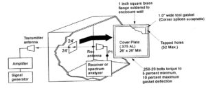
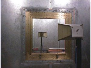
A first measurement is made from one antenna to the other through the opening and a second is made when the opening is closed by means of a metal plate with the gasket to be tested mounted around and compressed. The method measures the field before and after the metal/gasket and the shielding effectiveness of the gasket is: 20 log E1/E2 (H1/H2) or the difference between both measurements in dB from 20 MHz to 10 GHz.
The method has a theoretical repeatability of +/- 6-10 dB. However, repeatability can deteriorate to +/- 20 dB with small variations of the antenna position when half the wavelength is getting close to the characteristic dimension of the shielded room (change of antenna in the course of testing for each of the 3 decades). Another issue is the size of gaskets that can be tested by this method. The overlap of the heavy metal plate onto the shielded room wall induces capacitive coupling which effect the measurement when the gasket is small. There are other issues such as the size of the opening and its attenuation, the frequency limitation, the influence of the metallic screws (replaced sometimes by isolated clamps), etc. In practice, absolute values of SE should be taken very cautiously for the various reasons explained. It is observed that offset with actual values obtained in applications, increases with the frequency. The main interest of the method is probably that it is a standard so that measurements according to Mil DTL 83528C can be compared and especially if testing was carried out by an independent Laboratory. The specification requires a minimum of 5 measurements per decade and very often, technical documentation on gaskets provides the average value of the 15 measurements.
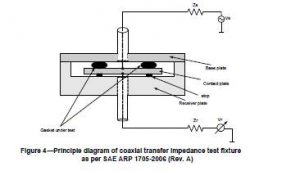
The other main standard is SAE ARP 1705, a current injection method measuring transfer impedance. When an Electromagnetic field impinges onto a metal barrier, it induces a current which in turn creates a voltage across the seam which radiates.
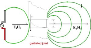
In the transfer impedance measuring technique , a current , supposedly resulting from the coupling with an electromagnetic field, is directly injected into the gasketed joint. The voltage across the seam is therefore measured. The ratio voltage over current reported in a 1 meter length defines the transfer impedance of the gasket expressed in dB Ohm/m . The current injection method has a good repeatability of +/- 3-6 dB. SAE ARP 1705 Rev. A is limited to 1.5 GHz and a revision C is in progress which should extend the frequency range to 10 or 18 GHz. The measuring fixture can easily be modified to accommodate modules of different metals so that the degradation of contacts can be studied under different aging conditions. This method provides a direct indication of the conductivity of the gasketed joint but discussions are still ongoing into the relationship between transfer impedance and shielding effectiveness. In the Shelkunoff model ,the overall attenuation into a material is the sum of reflection and absorption factors. The reflection factor is actually not considered in the transfer impedance.
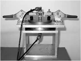
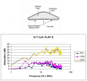
For the measurement of Shielding Effectiveness for small size gaskets, TEM-T and Ht Cells method is preferred. This is a non-standardized test method described in IEEE Std 1302 and used in R&D because of its good repeatability (1-3 dB). TEM-t is a TEM mode transmission line device simulating far field conditions. The square coaxial fixture of the TEM-t is cut in the middle so that a gasket holder compressing the gasket under test can be inserted between the two halves of the measuring equipment. The H-t cell is made by a set of two small loop antennas simulating the magnetic near field.


In the following example, the Ht cell was used to evaluate the influence of a small deformation at the bottom (bump) of a Fabric-over-Foam D-shape gasket compared with a standard flat bottom one. The modification is intended to improve the efficiency at low compression in combination with non conductive pressure sensitive adhesive. SE measurement were taken at 0%-10%-20% compression (from the free height of the gasket). The gasket, SEM’s DYNASHEAR EJ9, is 2.3 mm high so that 10 % compression represents a variation of only 0.23 mm in height. The results show that for a flat bottom gasket, a minimum compression of 20% must be applied to overcome the isolated layer of adhesive while with a small bump at the bottom, substantial SE is already obtained at low compression. H-t cell is an excellent method to characterize SE for such little variations of compression and for such a small size gasket. The absolute SE is not very high but it is mainly due to the short distance between the antenna and the gasket and therefore the low mismatch between the characteristic impedance of the magnetic field and the intrinsic impedance of the gasketed joint. The frequency range is 100- 500 MHz.

Most Electronic Equipments are working at higher speeds than in the past and with the latest technologies, systems take less and less space. Proximity creates new challenges with more cross-talk between circuits affecting the functions of equipment so that signal integrity has become more challenging, much more than just shielding for the compliance of equipment to a specific standard. In the US, for radiated measurements, FCC (Title 47 part 15.33) requires for systems with the highest frequency over 1GHz, to test to the 5th. harmonic or 40 GHz (whichever is the lowest). Testing Electronic equipment to 40 GHz starts to be very common in specific fields of Electronics. As one can see, there is a major gap between standards available to the gasket industry and the market requirements. For that reason a technical committee started to work on the revision and the extension of the IEEE Std 1302 from 18 GHz to 40 GHz. At the time of writing, there are not too many works in progress for the characterization of EMI gaskets up to 40 GHz. The major one is the stripline method.
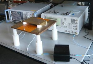
Schlegel Electronic Materials, in partnership with Prof. J.Catrysse and Prof. D.Pissoort of the KULab REMI research group of the KULeuven (University of Leuven-Belgium), developed a new testing fixture to characterize the Shielding effectiveness of conductive gaskets up to 40 GHz. The principle of this fixture is based on a method that was first introduced by Prof. B. Koerber to measure the radiated emission and susceptibility of Integrated Circuits (IEC 61967-8 and IEC 62132-8). The method utilizes a stripline antenna which closes over a PC-Board.

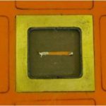
In the new stripline fixture, the PC board with the IC under test is replaced by a small microstrip antenna embedded into a cavity within the ground plane. The cavity can be closed by means of a thick plate which compresses the gasket under test. A stripline antenna covers the set-up.
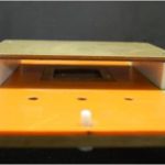
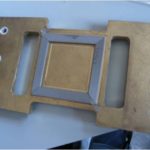
The testing procedure , similar to IEEE 299 or Mil DTL 83528 C, is as follows:
1) a direct measurement from microstrip to stripline to establish a reference (measurement of the signal before the shield).
2) measurement of the closed cavity with the gasket under test (measurement of the signal after the shield)
3) Difference between both measurements in dB is the Shielding Effectiveness of the gasket.
Repeatability is excellent even if the signals are noisy. We can see on the hereafter graphs the SE obtained from 1 to 40 GHz for one fabric-over-foam gasket 3 by 9 mm, and one metal fingerstock D- shape of same dimension but with a slot of 0.45 mm and a finger width of 4.32 mm. Both were compressed to 50 % from free height. The fabric-over-Foam gasket has a pretty steady response while the metal gasket displays a continuous drop from 12 GHz because of the slot between the fingers. The attenuation will vary as a function of the slot pattern and the stripline fixture is an interesting mean to figure out its impact on SE at high frequency.


Another example is the SE measurement of an I/O connector gasket made of conductive fabric over a non conductive foam core. The gasket is fabricated to the required width and then die-cut according to the dimensions of the connector shell. This type of solution worked fine in the past when most of the issues were in the 300 MHz region. The stripline method shows that this solution works up to 1 GHz. In fact with the frequency increase, openings created with the die-cut of non conductive foam core are leaking and sometimes the impedance of the return current path between flanges may even create antenna effect .The stripline method shows that by using a conductive fabric over a Z conductive foam core, large improvements are obtained. At low frequency the fabric brings the major contribution and as the frequency rises, the Z conductive foam core ensures a higher shielding and a shorter return current path making this gasket construction a broadband solution (SEM Ref. ORS-II).


The stripline method features some other interesting characteristics. The microstrip antenna being a trace on a board, the PC board environment is reproduced so that the data obtained can be expected in a similar environment. For that reason, the method may be considered in the future for the characterization of PC-board shielded cans.
The test method will be soon supported by a standard from SAE (Society of Automotive and Aerospace Engineers) under the reference SAE ARP 6248 .
REFERENCES
IEEE Std 1302 –Rev. 2008 : IEEE Guide for the Electromagnetic Characterization of Conductive Gaskets in the Frequency Range of DC to 18 GHz
Catrysse, F. Vanhee, D. Pissoort, C. Brull, and G. Vandenbosch, “A new stripline measuring setup for the characterisation of conductive gaskets up to 18 GHz”, Proceedings of the IEEE International Conference on Electromagnetic Compatibility, Fort Lauterdale, Florida, USA, July 2010,
Catrysse, F. Vanhee, D. Pissoort, C. Brull, and P. Reynaert, “Expanding the Stripline Measuring Set-up for the Characterisation of Conductive Gaskets up to 40 GHz”, Proceedings of the IEEE International Conference on Electromagnetic Compatibility, Pittsburgh, Pennsylvania, USA, Aug. 2012
J.Catrysse, T.Grenson, F.Vanhee, D.Pissoort and C. Brull, “The importance of continuous and homogeneous Gasket Conductivity up to 40 GHz”, Proceedings of EMC Europe 2013 Brugge Symposium, Brugge, Sept. 2013
Schelkunoff, S. A., Electromagnetic Waves. New York: Van Nostrand, 1943.


