Proposed changes to IEC 61000-4-2 will be adopted during 2009.
Nicholas Wright, EMC Partner AG, Laufen, Switzerland
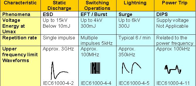
IEC 61000-4-2 covers the immunity requirements and test methods for electrical and electronic equipment subjected to static electricity discharges. Additionally, it defines ranges of test levels appropriate for different environmental and installation conditions and establishes test procedures to be followed. The object of the standard is to establish a common and reproducible basis for evaluating the performance of the equipment when subjected to electrostatic discharge following the methodology set forth in the standard. (See overview in Figure 1.) In fact, IEC 61000-4-2 has been used for many years and is an evolution of the IEC 801-2 standard that dates from 1988. Today, in light of modern measurement methods, and given the experience gained over the last 30 years, changes to the standard have been proposed and will be adopted during 2009.
REASONS FOR REVISION
Using modern test equipment and the provisions of the current standard, it has been found that any EUT (equipment under test) could either pass or fail based on the type of simulator that is used. In other words, know which simulator to choose, and there is no actual test, just an assured outcome. Also, new high-speed technology is now in use that operates into the GHz range. MT12, the International Electrotechnical Commission (IEC) Maintenance Team responsible for ESD standards, has issued a CD (Committee Draft) proposing the following changes:
- A clearer definition of the calibration and verification of measurement equipment;
- A mathematical equation of the standard current waveform;
- A definition of uncertainty for different parameters;
- The elimination of tests for contact discharge at lower level.
THE “GOOD OLD DAYS”
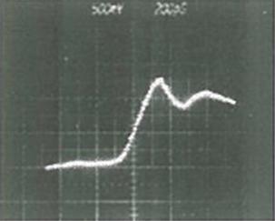
Before the world of electronics reached its present “high-tech” status, ESD (electrostatic discharge) was a fairly straightforward affair. Anything resembling the specified waveform that “magically” (and unexpectedly) appeared on the analog oscilloscopes was acceptable, and nobody could do anything to prove it otherwise. See Figure 2. Still, technology moves on; and with the advent of digital oscilloscopes, bandwidths increased. Suddenly, the light dawned, and the old ways of ESD testing no longer would do. With the advances in ESD testing and the growing realization that ESD test results seemed to vary from place to place, standards organizations were impelled to investigate further.
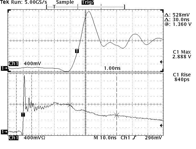

Various “remedies” were proposed to improve the situation. One of these was an attempt to modify the waveform tolerances by controlling the waveform within much tighter limits and by eliminating high frequency ringing. Additionally, a series of round-robin tests on six EUTs was conducted at different international locations using both the existing and modified simulators. The problem was that no correlation could be found. To start with, the EUTs did not exhibit failures when subjected to the standard ESD test levels. Compare Figures 3 and 4.

Also, huge variations were observed as a result of changing the ESD simulator model. Even using modified simulators did not show any improvement over using unmodified models. Significantly, no direct correlation could be found between current, field, or frequency related parameters and the EUT failure level. As the final “nail in the coffin,” test results varied even when using ESD simulators from exactly the same manufacturer. Notice the varying results shown in Figure 5.
AN ESCALATION STRATEGY
As no definitive source could be identified that explained all the differences observed, a new approach had to be adopted for the whole test process. This involved several steps. First the test setup was verified including all the details—the position of each cable and the condition of the EUT and its doors and covers. Then the test procedure itself had to be verified including the operation mode of the EUT, the position and location of auxiliary equipment, operator position, software state, and application of discharges to the EUT. Finally, attention was turned to the test simulator itself. Was it operating correctly? When was it last calibrated? Was it operating within specifications? Could varying test results be attributed to the use of different simulators?
Consideration of these questions led to two problematic implications. If different test results could be obtained by using different ESD simulators, why not simply choose one that met the requirements of 3.1 and that brought about the desirable test result of compliance with the standard? A narrow, literal reading of the standard allows relying on the test results obtained using an ESD simulator that is less “aggressive” to the EUT. Still, important concerns remained. Quality, reliability, and customer satisfaction are all important to successful marketing of a product so it might well be advisable to guarantee that the EUT will deliver error-free performance by testing it with the more formidable simulator.

A strategy for an escalated testing regime was formulated. First, if more than one error occurred during the first 50 discharges applied to a test point, the EUT failed at that test point and test level. If one error did occur during the first 50 discha rges applied to the test point, a second test of 100 discharges was carried out. If no error occurred during this process, the EUT has passed the test at that test point. Conversely, if more than one error occurred, the EUT failed at that test point. If exactly one error occurred, a third test was performed. The third test was simply a repetition of the second test, and the same criteria applied. No error is passing, and more than one error results in failure.
Adoption of the measures outlined above is intended to increase the reliability and repeatability of test results and to eliminate the “rigging” of compliance testing by a savvy choice of ESD simulator. The immediate effect for testing personnel is a dramatic increase in testing time. Laboratories that charge by the hour should be delighted by this result.
PROPOSED NEW TARGET
Another effort to improve the reliability of ESD testing is a new calibration procedure with an updated target. In the late 1980s, the existing Pelligrini target represented the height of technology with a bandwidth of 1 GHz (Figures 6 and 7). As the years passed and bandwidths increased a similar pattern of increase could be discerned in test discrepancies. It became evident that a matched higher bandwidth chain was needed. The revised target bandwidth is 4 GHz (Figures 8 and 9).

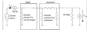
In the schematic terms shown in Figure 10, ZSYS = V50 / ISYS and therefore, IESD = VESD / ZSYS

ZSYS must be used to calculate the ESD current. V2 is a factor 2 higher because of the missing 50 Ohm.
Because of the high bandwidth and very tight tolerances on variation across the frequency range, any discontinuity will have a significant effect on frequency response. Clearly, it is important to employ good RF engineering practices and to calibrate the target as well as any cables and connectors necessary for the ESD calibration.

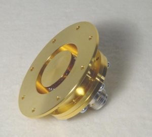
For the first time in an ESD standard, the calibration target has been carefully defined. As with any high frequency calibration measurement, the actual test equipment can be a significant factor and must be carefully considered. The standard does not specify the exact measurement equipment, but a network analyzer capable of measuring S-Parameters is practically indispensable. Another challenge is making a connection to the target that does not introduce electrical discontinuities. One possible solution is a conical adapter as shown in Figure 11 although other adapter shapes than conical are also acceptable.
NEW CALIBRATION PROCEDURE
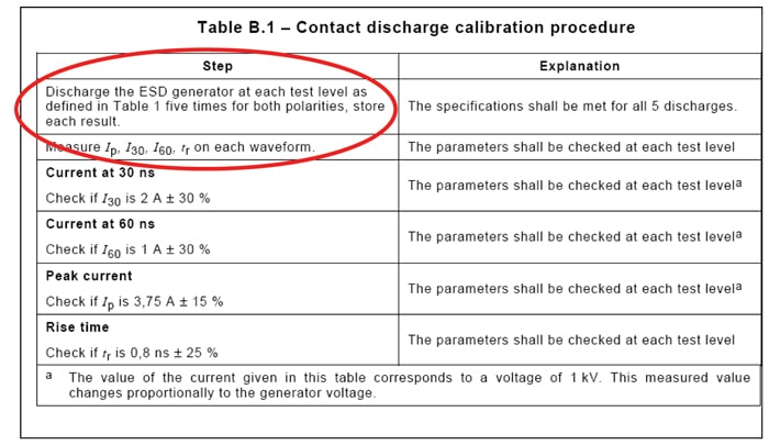
A new calibration procedure for ESD simulators has been devised to remove the “one shot wonder” approach by specifying the exact number of discharges and levels to be verified. This approach, like the new test procedure, will increase the time necessary to calibrate ESD simulators. Consider: 5 discharges x 2 for each polarity x 4 test levels = 40 impfulses minimum.
This simple formulaic change will obviously mean more time in the calibration laboratory and a resultant increase in costs for ESD simulators. Note the step-by-step requirements shown in Figure 12.
THE SIMULATOR ITSELF
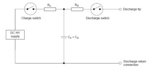
The coming changes do not impact the ESD simulators themselves. The new requirement simply references the older standard—i.e., ESD simulators shall meet the requirements given in paragraph 6.1, of IEC 61000-4-2 Ed. 2, when evaluated according to the procedures in Annex B of the standard. Consequently, the coming changes will not include a simulator schematic as shown in Figure 13, nor will any element values be specified in detail. The intent of these omissions is that ESD simulators should be defined in terms of wave-form shape rather than specific components, and existing simulators should have no trouble complying with Ed. 2 requirements.
USING THE 20-HZ DISCHARGE REPETITION
Note 1 indicates that the voltage should be measured at the point of discharge. This practice has been a point of controversy for many years. The only way to be absolutely certain that the voltage is as specified (assuming the ESD indication is overlooked) is by using an external measurement device. Note 2 is specifically intended for finding weak spots in the EUT. Because of the electrical-mechanical switches used in ESD simulators, the 20-Hz test is best performed in air discharge mode. On a cautionary note, such a high repetition reduces the life span of the high voltage relay.
CONCLUSION
Electronic products have changed significantly over the last thirty years. New technology is in use that operates in the GHz range. Testing to the long established ESD standard IEC 61000-4-2 is no longer a viable option. Widespread discrepancies in test results have made it evident that a matched, higher frequency measurement chain should be used. Clearly defined calibration targets are vital as well. These improved escalated test requirements will be adopted during 2009.
Nicholas Wright was educated at Worcester College, England. He has worked on military projects for the UK M.O.D, Marconi and GEC Avionics. Moving into the field of EMC, he has held posts as product manager and regional sales manager, culminating in his current position as international sales manager for EMC Partner based in Switzerland.


