Dear readers, I have been really busy working in training and EMI troubleshooting in the past months. I am happy to be here again with a new post.
This month we will see a topic from a real-world situation – very interesting – for electronic designers working in conducted emissions problems.
In one of the projects I was involved with several weeks ago, a product was failing in conducted emissions on an AC power supply line. Measuring with a LISN (Line Impedance Stabilization Network), the problem was related to common mode emissions.
The designer of the circuit tried to work with a common mode choke to reduce emissions (Y capacitors were not possible for this application).
He was using a low cost (this is important!), common mode choke using toroidal core.
For that component he had several samples for testing and, initially, the choke looked like an effective solution in the trials inside of the company. Let’s name the choke used CHKA.
With the promising result in the company, a prototype was specially prepared to go to an external lab (time to cross our fingers!).
But, in the external lab the product failed again (I think you have experimented similar situation), and a typical question comes to your mind: “How is it possible that the solution in the company was failing in the external lab?”
The answer to that question lies, as usual, in discovering what is different between both scenarios.
Analyzing the problem, I discovered that the choke used in the prototype for the external lab was a different unit from that soldered in the original prototype. Same part number, same manufacturer, same samples box, but …. a different unit, not EXACTLY the choke used in the company. Let’s name the second choke CHKB.
Before explaining the reason for the failure, let’s review the basics of a common mode choke.
A common mode choke is a coupled inductor: two inductors are built using the same core. Note the winding strategy (Fig. 1) is very important to obtain a common mode choke.

Fig. 1. Ideal common modes choke for differential currents (left), common mode currents (mid), and symbol for schematics (right).
For this ideal choke, the magnetic flux in the core is because the differential mode currents iDM (Fig. 1, left) cancel each other resulting in a zero impedance. But magnetic flux caused by common mode currents iCM (Fig. 1, mid), is accumulated resulting in a high amount of impedance value. The symbol for this kind of choke (Fig. 1, right) uses two points to specify how the windings must be done to obtain that behavior.
Summarizing, an ideal common mode choke looks like a simple wire for differential mode signals while it looks like an inductor for common mode signals. One of the advantages of these kinds of chokes is they will not be saturated by differential mode currents.
For those coupled inductors, coupling factor k can be calculated from Eq. 1:
k = M/√(L1×L2) (Eq. 1)
and common mode and differential mode inductances can be obtained from Eq. 2:
LDM = 2×(L-M) and LCM = (L+M)/2 (Eq. 2)
where M is mutual inductance and L1, L2 are inductances for both inductors.
Considering the inductors are equal, L1 = L and for 100% of perfect coupling k=1, mutual inductance M is from Eq. 1 equal to inductance L (M=L) and common and differential mode inductances are from Eq. 2, LDM =0 and LCM = L.
So, it is confirmed that we will find not impedance effect for differential mode signals and some value of impedance for common mode signals.
In a real common mode choke the cancellation is not perfect. As a result, the differential mode impedance is not zero. This effect is sometimes called “leakage”. This is useful for filtering differential mode signals but the saturation effect must be checked in high current applications.
Let’s go back to our example failing in the laboratory. To analyze the situation, I measured the response of both chokes with my Bode 100 network analyzer (a really useful instrument if you are interested in frequencies up to 50MHz).
A simplified measurement of a common mode choke can be done as shown in Fig. 2:

Fig. 2. Simplified measurement of impedances for a common mode choke.
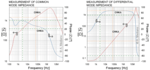
The choke working satisfactorily in our application (CHKA) was measured and results are in Fig. 03:

Fig. 3. CHKA simple characterization.
You can see how big the impedance of the common mode effect is when compared with the differential mode effect.
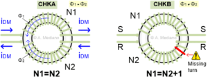
For the second choke (CHKB), the one failing in the laboratory, I was able to see a very subtle difference: one of the coils of the choke had ONE TURN missing (Fig. 4).

Fig. 4. The chokes used in our example.
CHKA had 14 turns for L1 and L2. CHKB had 14 turns for L1 and 13 turns for L2.
This is a very critical difference. If one of the coils is not exactly as the other, the common mode inductance will be reduced (poor common mode filtering) and the differential inductance will increase (perhaps the core can be saturated with the nominal current in high current applications).
This kind of cores are manually winded so human errors and/or low-quality tests can create this difficult to find problem.
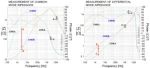
The comparison of both chokes is included in Fig. 5:

Fig. 5. Comparing chokes CHKA and CHKB.
From the measurements, it is clear how important a perfect symmetry for the two coils in the choke. With only one turn missing in one of the coils the common mode impedance (Fig. 5, left) is drastically reduced, as for example from point A to point B at the same specific frequency. The result will be a lower effectiveness to filter common mode EMI signals.
In the same way, the differential mode inductance increases from A to B (Fig. 5, right) with a typical effect of saturation of the core.
Let me conclude this post with two important pieces of advice: 1) be careful with low cost/low-quality components; and 2) try to have a network analyzer or impedance analyzer in your laboratory to check how the component you are using in your design is. And of course, good luck in your next design!


